Why Power Utility Transformer Monitoring Requires an Application-Specific Scope
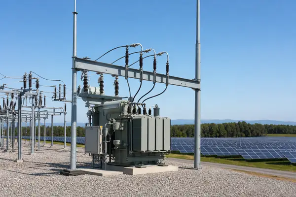
Power Utility Transformer Monitoring is not simply a list of available sensors. The monitoring scope must reflect transmission and distribution substations where transformer availability, loading margin and maintenance access are operational priorities. The first engineering task is to identify which changes could affect availability, safety, loading decisions or maintenance timing.
A useful scope connects every measured parameter to a decision. If the response to a temperature, gas, discharge or mechanical trend is undefined, adding more channels can create noise rather than confidence.
Transformer Assets and Boundaries
The typical monitoring boundary includes large oil-filled power transformers and their bushings, tap changers, cooling groups and insulation systems. Auxiliary systems, communications, power supplies and local environmental conditions also influence whether the data remains dependable.
Project drawings should identify transformer type, ratings, cooling arrangement, existing instruments, sensor access, control interfaces and outage restrictions. This prevents a generic package from being specified without regard to installation reality.
Priority Failure Modes and Operating Risks
The risk review should consider thermal aging under sustained or cyclic load; insulation faults that develop between inspection intervals; bushing and oltc deterioration outside the main tank; scattered data that does not support a clear maintenance response. These concerns do not have equal probability or consequence on every transformer, so the final priority should be agreed by the owner and engineering team.
Monitoring does not replace protection, inspection or diagnostic testing. It adds time-based evidence that can help teams recognize deviation, plan confirmation work and respond before a condition becomes harder to manage.
- Thermal aging under sustained or cyclic load
- Insulation faults that develop between inspection intervals
- Bushing and OLTC deterioration outside the main tank
- Scattered data that does not support a clear maintenance response
Recommended Monitoring Architecture
Establish a thermal, chemical, electrical and mechanical monitoring scope from credible failure modes. Trend temperature, dissolved gas, partial discharge, bushing and OLTC indicators in operating context. Integrate actionable alarms with station systems while retaining diagnostic records. Local acquisition should preserve raw or diagnostic data needed for review, while station systems receive concise status, alarms and selected trends.
A layered architecture normally includes sensors, field acquisition, local calculation or alarm logic, communication interfaces and a maintenance-facing record. Redundancy and cybersecurity requirements should be defined by the asset owner.
Sensors and Measured Parameters
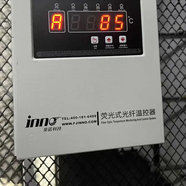
Sensor selection starts with the physical indicator and the measurement location. Direct winding temperature, top-oil temperature, fault gases, partial-discharge signals, bushing electrical indicators and OLTC signatures describe different parts of transformer condition.
The specification should state range, channel count, installation method, insulation requirements, expected accuracy, output protocol and environmental rating. It should also identify values that are measured directly and values that are calculated.
Alarm Strategy and Data Interpretation
Initial alarm settings should consider transformer design information, established owner practices and commissioning baselines. Rate of change, persistence and agreement with related parameters are often more informative than one isolated value.
An alarm should lead to a defined review path: verify instrument health, check load and ambient context, compare associated trends, then decide whether inspection, sampling or offline testing is required. The monitoring system should not be presented as an automatic final diagnosis.
SCADA and Remote Communication Integration
Before configuration, agree the protocol, tag list, units, timestamps, quality flags, alarm priority and communication ownership. Only decision-relevant values need to enter the primary control display; higher-resolution diagnostic records can remain in the monitoring platform.
Integration testing should verify value scaling, loss-of-communication behavior, time synchronization and alarm acknowledgement. These details are especially important where the transformer is remote or the response team is not located at the site.
Installation and Commissioning Considerations
Installation planning should cover sensor location, cable routing, feedthroughs, electromagnetic environment, auxiliary supply, enclosure position and safe access. Factory-installed winding probes require earlier coordination than retrofit tank, bushing or external sensors.
Commissioning should record sensor identity, channel mapping, baseline readings, simulated alarms, communication checks and any limitations. Photographs and marked drawings make later troubleshooting more efficient without making unsupported performance claims.
Procurement Information to Send FUZHOUINNO
A useful inquiry includes the transformer nameplate, application, installation stage, monitoring objectives, required parameters, channel count, available sensor points, communication protocol and project schedule. Drawings and existing instrument lists help avoid unnecessary assumptions.
FUZHOUINNO can review the requested measurement scope and propose compatible sensors, acquisition units and interfaces. Final placement, limits and maintenance actions remain project-specific and should be approved through the owner’s engineering process.
Limitations and Responsible Use
Condition monitoring reduces uncertainty but does not eliminate it. Sensor faults, installation effects, interference, sampling limitations and changing operating conditions can all influence readings. Important decisions should use corroborating evidence.
Alarm response, sensor placement and confirmation methods should be approved for the transformer design, operating environment and owner maintenance procedure.
Related Products, Solutions and Technical Guidance
- Power Utility Transformer Monitoring solution
- Matching transformer monitoring products
- Transformer monitoring system selection guide
Application guidance is for project scoping only. Final sensor locations, alarm settings and diagnostic actions depend on transformer design, operating history and owner procedures.