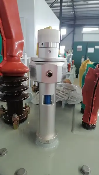
transformer oil condition monitoring system
Transformer Oil Condition Monitoring System
Integrated visibility into transformer oil temperature, level, pressure and configurable condition inputs.

Coordinate transformer oil temperature, level, pressure and moisture-related measurements for early operating-condition awareness.
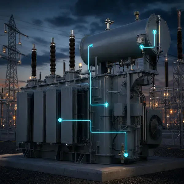
Compare available sensors and instruments that can support this project scope.
Integrated visibility into transformer oil temperature, level, pressure and configurable condition inputs.
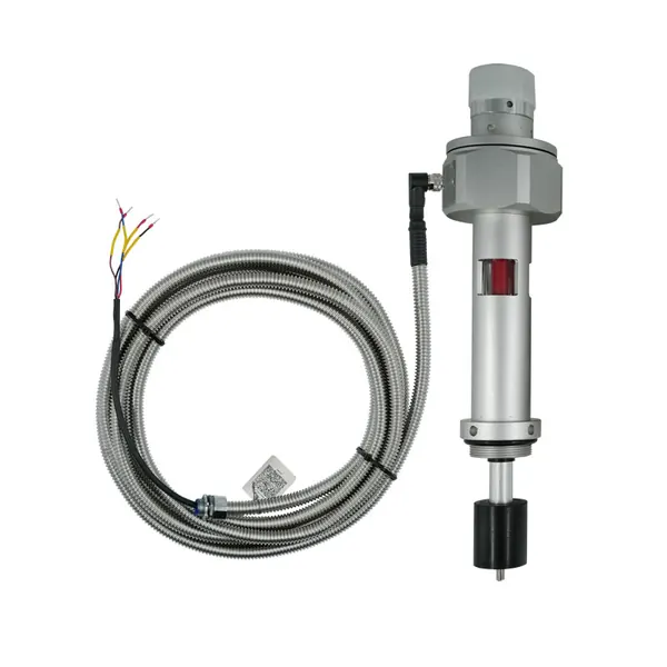
IP68 three-in-one transformer monitor for oil temperature, oil level and absolute pressure with RS-485 integration.
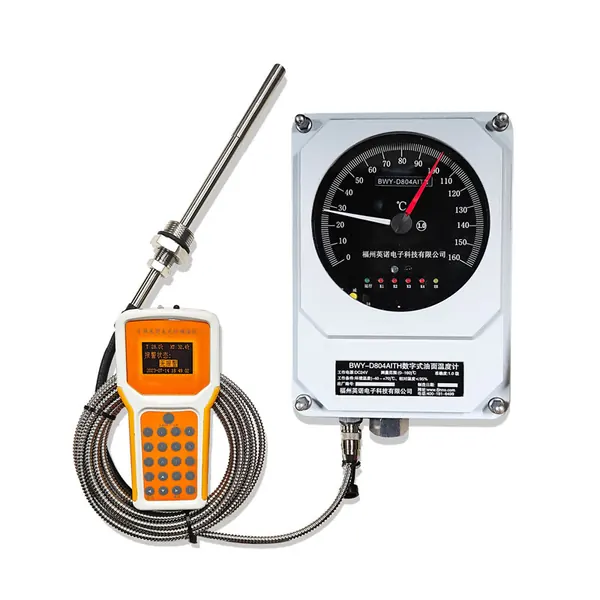
Local indication and remote signal options for conservator oil level and temperature.
transformer oil condition monitoring solution
Oil level, pressure, temperature and moisture change with transformer loading and tank design. Reading one value in isolation can turn a normal thermal movement into a false alarm or hide a leak.
Electronic gauges and sensors track bulk oil temperature, liquid level, tank pressure and moisture. The expected relationship depends on whether the transformer is conservator type, sealed tank or nitrogen-blanketed.
Local gauges, electronic transmitters and multi-parameter monitors are selected according to conservator, sealed-tank, flange and environmental requirements.
Oil-condition monitoring combines sensors that answer different questions: temperature describes thermal state, moisture affects dielectric margin, level follows the preservation system, and pressure can reveal abnormal tank or gas-space behavior.
| Parameter | Installation context | Interpretation context |
|---|---|---|
| Oil temperature | Top-oil pocket, flange or electronic sensor | Load, ambient and cooling stage |
| Moisture in oil | Oil loop or immersed probe | Oil temperature and equilibrium with paper |
| Oil level | Conservator or sealed-tank gauge | Temperature-volume relationship and float condition |
| Tank pressure | Sealed tank or pressure device | Temperature, relief operation and sealing system |
Sensors provide local indication, relay, analog or digital outputs to a field monitoring unit. The configuration should preserve local usability even when remote communication is unavailable.
Electronic gauges and sensors track bulk oil temperature, liquid level, tank pressure and moisture. The expected relationship depends on whether the transformer is conservator type, sealed tank or nitrogen-blanketed.
Oil level should normally move with temperature. If temperature falls but the electronic level continues to drop, compare the local gauge, inspect for leakage and verify float movement before treating the reading as a true loss of oil.
Trend related oil values together and record the tank arrangement. Confirm contradictory readings with the local instrument, visual inspection and an oil sample where needed.
Selection requires tank design, mounting dimensions, expected range, contact ratings, enclosure protection, cable entries, power and communication requirements.
Commissioning should prove each channel with a realistic input, confirm the channel name and units, simulate alarms and record the first usable baseline.
Temperature, level and pressure thresholds need operating-temperature context and suitable delays. Contradictory readings can indicate a sensor or installation issue rather than an asset fault.
Remote values and alarms may connect through 4–20 mA, relay or supported digital protocols. Tag descriptions should state the measurement point and reference condition.
Useful for remote transformer inspections, sealed-tank supervision and projects replacing mechanical indication with alarm and communication outputs.
Oil-system monitoring identifies abnormal conditions but does not replace oil laboratory analysis, leak inspection or a complete assessment of internal insulation condition.
Compare proposals line by line. Confirm the included sensors, cables, field equipment, software, drawings, commissioning work and communication interface instead of comparing only the monitoring host.
The final scope depends on transformer design and project objectives. It normally combines selected sensors, field acquisition, alarms, communications and an engineering response process.
Retrofit feasibility depends on sensor access and outage constraints. External measurements are usually easier to retrofit than winding sensors installed inside the active part.
Yes when the selected field equipment supports the required interface. The protocol, tag list, network responsibility and acceptance tests must be defined.
No. Online trends reduce information gaps, while offline tests, oil samples and inspections remain important confirmation tools.
Provide transformer drawings and ratings, installation stage, required measurements, communication architecture, alarm philosophy and project quantity.
Monitoring guidance is provided for project scoping. Final sensor placement, alarm settings, interfaces and diagnostic actions depend on transformer design and owner procedures.
Share the transformer design, measurement points, installation stage and communication requirements. FUZHOUINNO will review a suitable product and monitoring configuration.