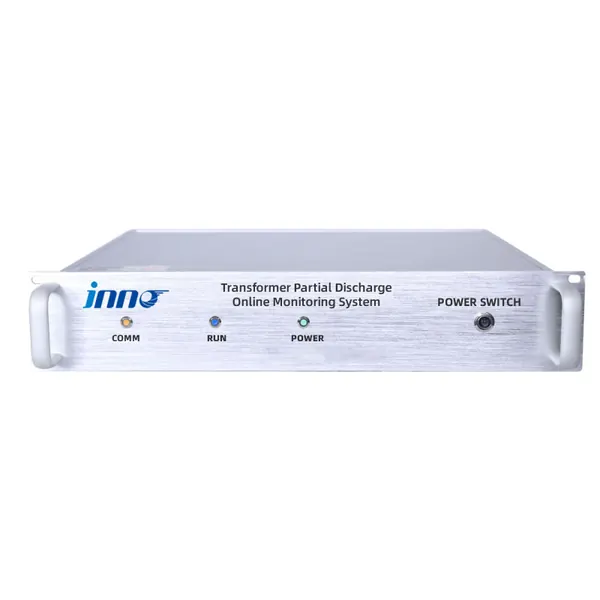
transformer partial discharge monitoring system
Transformer Partial Discharge Online Monitoring System
Online UHF, ultrasonic and pulse-current monitoring for transformer insulation discharge trending and early warning.

Combine UHF, ultrasonic and HFCT sensing with synchronized acquisition, PRPD patterns and persistent transformer PD alarms.
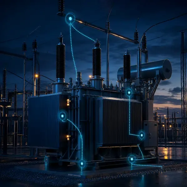
Compare available sensors and instruments that can support this project scope.
Online UHF, ultrasonic and pulse-current monitoring for transformer insulation discharge trending and early warning.
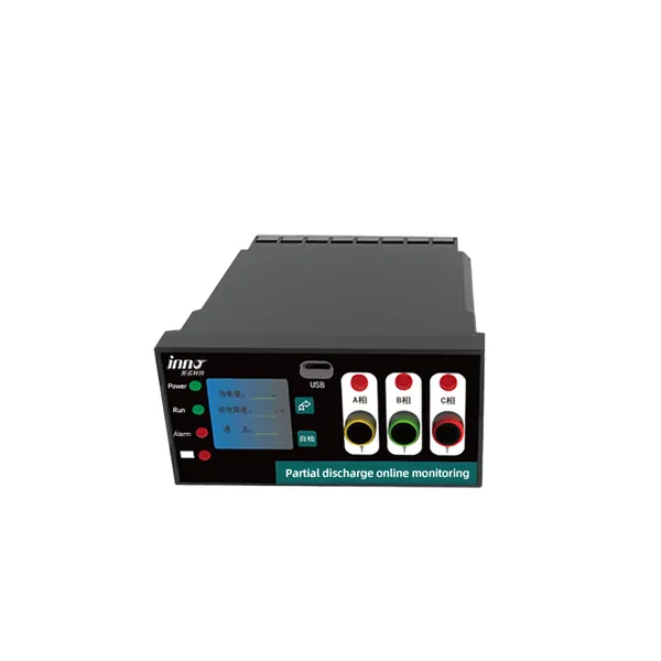
Combined electrical-discharge and thermal inputs for transformer and electrical equipment condition monitoring.
transformer partial discharge monitoring solution
Small insulation discharges can repeat long before breakdown, but a substation also contains radio, corona, switching and converter noise. A sensitive monitor without noise control can create more alarms than answers.
UHF sensors detect electromagnetic pulses, HFCT sensors detect high-frequency current on grounding paths and acoustic sensors detect stress waves at the tank wall. Synchronized channels and power-frequency phase reference help separate repeatable transformer activity from interference.
UHF, ultrasonic and high-frequency current sensors observe different aspects of discharge. Using complementary locations can improve confidence when the signals agree.
Partial-discharge monitoring captures high-frequency electromagnetic, current or acoustic manifestations of a localized insulation discharge. UHF sensors, HFCTs and ultrasonic sensors observe different propagation paths; synchronized channels, a power-frequency phase reference, PRPD/PRPS records and a site noise survey help separate repeatable insulation activity from interference.
| Method | Typical installation | Evidence produced |
|---|---|---|
| UHF | Approved oil valve, drain valve or designed antenna interface | Electromagnetic pulses in the selected UHF band; timing and PRPD trend |
| HFCT | Core ground, neutral or approved grounding conductor | High-frequency pulse current and arrival time |
| Ultrasonic / acoustic | Repeatable tank-wall or flange locations | Acoustic amplitude and relative arrival time |
| Electrical reference | Power-frequency voltage phase reference | PRPD phase position, magnitude distribution and repetition |
| Synchronized acquisition | Simultaneous multi-channel recording | Cross-channel correlation and localization evidence |
Synchronized field channels feed high-speed acquisition and pattern-analysis software. Installation geometry, cable quality, grounding and time reference affect the usefulness of comparisons.
UHF sensors detect electromagnetic pulses, HFCT sensors detect high-frequency current on grounding paths and acoustic sensors detect stress waves at the tank wall. Synchronized channels and power-frequency phase reference help separate repeatable transformer activity from interference.
A pulse cluster that appears on every channel at the same instant may be external interference. A source that is strongest near one tank location, repeats at consistent phase positions and grows with operating stress deserves closer review and possible localization.
Retain PRPD or PRPS records, gain, threshold, bandwidth, phase reference and sensor position. Compare several time windows before planning an outage or offline PD test.
Before selection, document tank valves, bushing and grounding access, expected interference, required channels, localization objectives and the process for expert review.
Commissioning should prove each channel with a realistic input, confirm the channel name and units, simulate alarms and record the first usable baseline.
A practical alarm strategy considers magnitude, repetition, phase pattern, persistence and background behavior. A single uncorroborated pulse should not be treated as a complete diagnosis.
SCADA normally receives system status and selected alarm or trend values, while detailed waveforms and PRPD records remain available to diagnostic software.
Use permanent PD monitoring where insulation failure has high consequence, where an existing concern needs trending or where access for repeated surveys is limited.
Online PD monitoring indicates suspicious activity but sensor sensitivity and interference vary by installation. Offline electrical tests or inspections may still be required to confirm a fault.
Compare proposals line by line. Confirm the included sensors, cables, field equipment, software, drawings, commissioning work and communication interface instead of comparing only the monitoring host.
The final scope depends on transformer design and project objectives. It normally combines selected sensors, field acquisition, alarms, communications and an engineering response process.
Retrofit feasibility depends on sensor access and outage constraints. External measurements are usually easier to retrofit than winding sensors installed inside the active part.
Yes when the selected field equipment supports the required interface. The protocol, tag list, network responsibility and acceptance tests must be defined.
No. Online trends reduce information gaps, while offline tests, oil samples and inspections remain important confirmation tools.
Provide transformer drawings and ratings, installation stage, required measurements, communication architecture, alarm philosophy and project quantity.
Monitoring guidance is provided for project scoping. Final sensor placement, alarm settings, interfaces and diagnostic actions depend on transformer design and owner procedures.
Share the transformer design, measurement points, installation stage and communication requirements. FUZHOUINNO will review a suitable product and monitoring configuration.