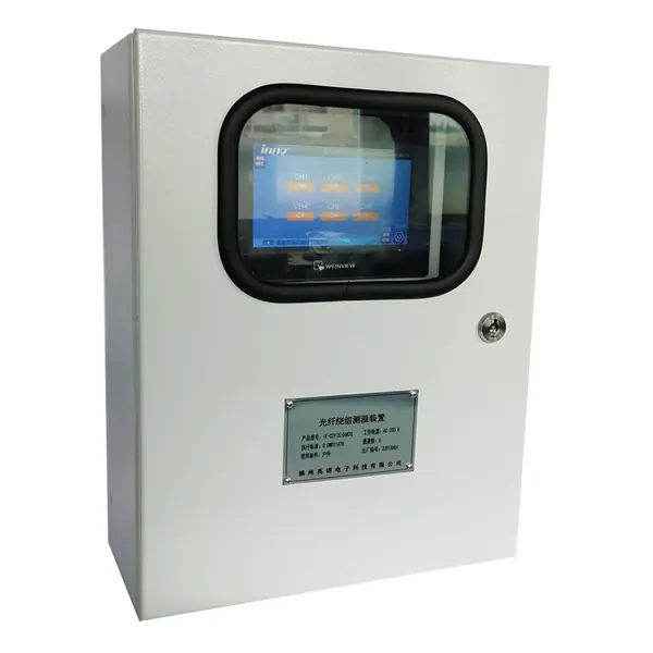
transformer temperature monitoring system
Oil-Immersed Transformer Temperature Monitoring System
Multi-point thermal monitoring for oil-filled transformer windings, oil and associated cooling equipment.

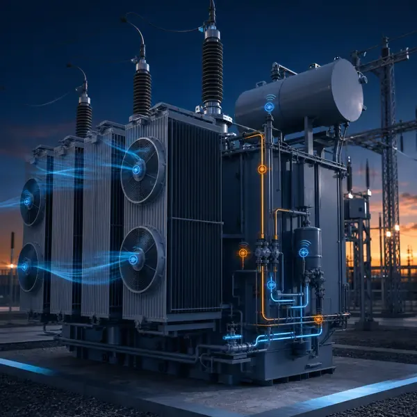
Monitor transformer fans, pumps, oil and winding temperature to identify abnormal cooling response and coordinate control stages.
Compare available sensors and instruments that can support this project scope.
Multi-point thermal monitoring for oil-filled transformer windings, oil and associated cooling equipment.
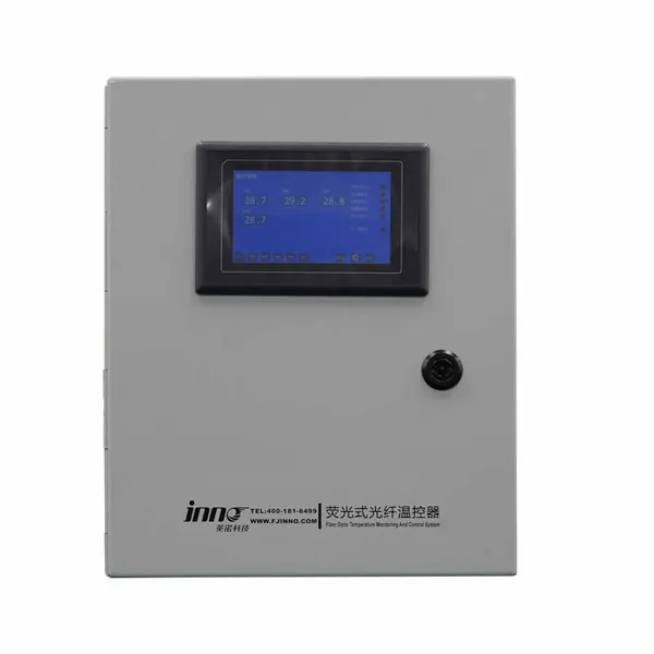
Online winding temperature and alarm monitoring for cast-resin and air-cooled dry-type transformers.
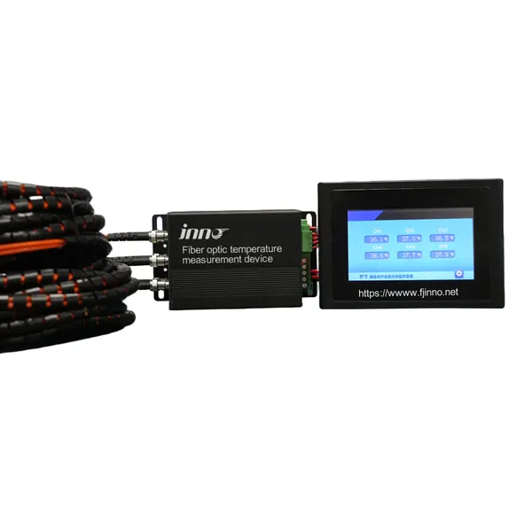
A configurable optical signal monitor for multiple transformer temperature probes.
transformer cooling system monitoring
A fan or pump command does not prove that air or oil is moving. Failed contactors, blocked radiators and incorrect stage feedback can leave the transformer heating while the controller reports cooling on.
Cooling monitoring compares temperature and load with stage commands, motor current, feedback contacts and the thermal response after a stage change.
Temperature sensors are combined with current, contact or status inputs from fans, pumps and control circuits. The exact signals depend on the cooling arrangement.
Cooling monitoring aligns temperature and load with fan, pump, valve and stage commands. It checks whether the commanded cooling equipment actually operates and whether temperature responds within the expected time.
| Observed item | Abnormal pattern | First confirmation |
|---|---|---|
| Fan or pump current | Command present but no operating current | Contactor, motor supply and feedback contact |
| Stage feedback | Command and feedback disagree | Control circuit and auxiliary contacts |
| Thermal response | Temperature continues rising after stage start | Airflow, oil flow, radiator and sensor context |
| Unexpected running | Cooling runs without demand | Controller setting, stuck contact or feedback fault |
A controller or monitoring unit records commands, feedback and thermal response on a common time base. Local automatic control remains coordinated with remote supervision.
Cooling monitoring compares temperature and load with stage commands, motor current, feedback contacts and the thermal response after a stage change.
When stage two is commanded, current feedback should appear and temperature rise should slow. A command with no current points toward the electrical drive; current with no thermal response points toward airflow, oil flow or heat-transfer problems.
Separate failure-to-start, feedback mismatch and poor-cooling-performance alarms. Inspect the relevant fan, pump, contactor, radiator or valve according to the failed check.
Scope definition requires cooling class, fan and pump groups, control voltage, existing thermostat logic, available feedback, ambient range and desired control responsibility.
Commissioning should prove each channel with a realistic input, confirm the channel name and units, simulate alarms and record the first usable baseline.
Useful alarms include failure to start, unexpected running, stage mismatch, excessive temperature rise and poor cooling response after a command.
SCADA can receive temperature, active stage, fan or pump status and cooling alarms. Control authority and remote-command permissions must be explicitly defined.
Useful for forced-air and forced-oil transformers, high-load sites and remote substations where cooling failures may otherwise remain unnoticed.
Monitoring can reveal abnormal cooling behavior but cannot quantify every internal flow restriction without further inspection and transformer-specific analysis.
Compare proposals line by line. Confirm the included sensors, cables, field equipment, software, drawings, commissioning work and communication interface instead of comparing only the monitoring host.
The final scope depends on transformer design and project objectives. It normally combines selected sensors, field acquisition, alarms, communications and an engineering response process.
Retrofit feasibility depends on sensor access and outage constraints. External measurements are usually easier to retrofit than winding sensors installed inside the active part.
Yes when the selected field equipment supports the required interface. The protocol, tag list, network responsibility and acceptance tests must be defined.
No. Online trends reduce information gaps, while offline tests, oil samples and inspections remain important confirmation tools.
Provide transformer drawings and ratings, installation stage, required measurements, communication architecture, alarm philosophy and project quantity.
Monitoring guidance is provided for project scoping. Final sensor placement, alarm settings, interfaces and diagnostic actions depend on transformer design and owner procedures.
Share the transformer design, measurement points, installation stage and communication requirements. FUZHOUINNO will review a suitable product and monitoring configuration.