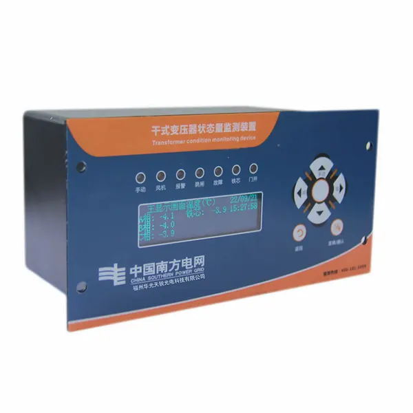
transformer online monitoring system
Dry-Type Transformer State Monitoring Device
Integrated dry-type transformer temperature, load and operating-status monitoring for condition-based maintenance.

A configurable sensor-to-SCADA approach for continuous transformer condition data, alarms and engineering review.
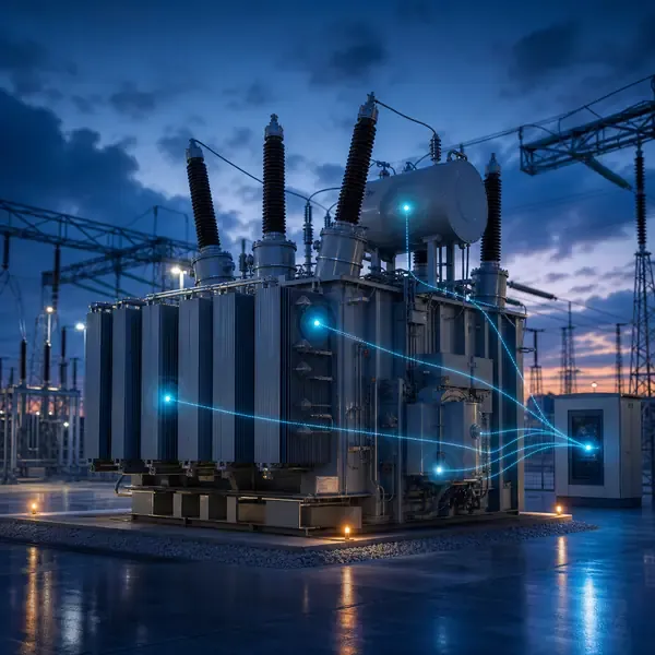
Compare available sensors and instruments that can support this project scope.
Integrated dry-type transformer temperature, load and operating-status monitoring for condition-based maintenance.
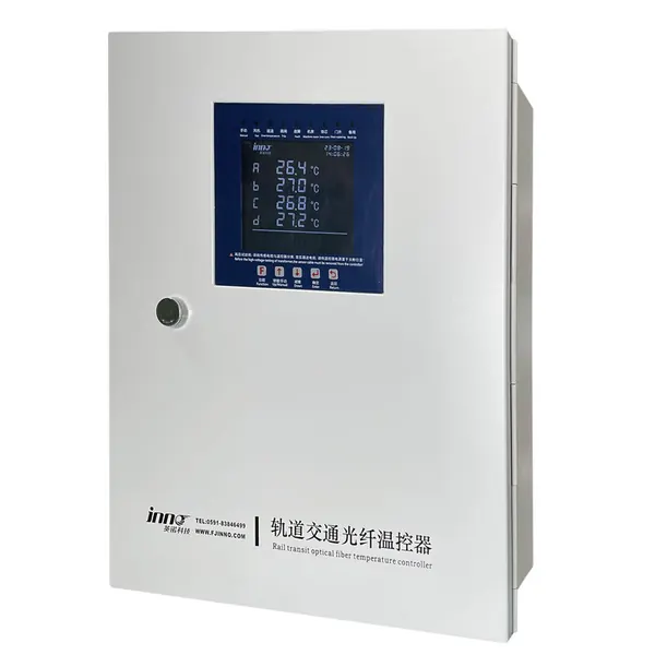
Transformer winding temperature monitoring configured for rail power and traction environments.
transformer monitoring solution
A transformer can pass a scheduled inspection and still develop overheating, gas generation or insulation activity before the next visit. Separate gauges make the problem harder because no one sees the measurements on the same timeline.
An online system brings selected temperature, oil, gas, discharge and mechanical signals into field acquisition equipment. Each channel keeps its own sampling method, device status and history while the control room receives a smaller set of alarms and operating values.
Sensors are selected by failure mode and practical installation access. Direct winding probes are normally planned during manufacture or overhaul, while several tank, bushing, grounding and oil-loop measurements may support retrofit projects.
An online system combines signal-specific sensors with field acquisition, local diagnostics, time synchronization, storage and a controlled SCADA interface. Temperature, gas, discharge and mechanical channels retain different sampling rates and diagnostic records.
| Monitoring layer | Concrete function | Acceptance evidence |
|---|---|---|
| Sensor layer | Measures a defined physical parameter at a named location | Drawing, sensor ID, range and realistic reading |
| Field acquisition | Conditions, timestamps and stores the signal | Channel map, clock check and retained history |
| Alarm layer | Applies threshold, persistence and device-health rules | Simulated advisory, warning and sensor-fault events |
| Station interface | Publishes selected values, quality and status | Approved tag list and communication-loss test |
Field sensors connect to acquisition units located close enough to preserve signal quality. The field layer conditions and timestamps measurements before selected values, alarms and health indicators are passed to the station system.
An online system brings selected temperature, oil, gas, discharge and mechanical signals into field acquisition equipment. Each channel keeps its own sampling method, device status and history while the control room receives a smaller set of alarms and operating values.
A rising top-oil temperature is not automatically a cooling fault. If load is rising and the next fan stage starts normally, the response may be expected. If temperature continues to climb after the fan command, current feedback and stage status should be checked before the operator increases loading.
Check the affected channel, compare related measurements and confirm the operating state. The alarm procedure should then name the inspection, oil sample or offline test required for escalation.
Scope definition begins with asset criticality, transformer drawings, existing instruments, outage access, monitored failure modes and the maintenance team that will act on the data.
Commissioning should prove each channel with a realistic input, confirm the channel name and units, simulate alarms and record the first usable baseline.
Alarm design separates sensor faults, threshold excursions, rate-of-change events and persistent multi-parameter changes. Operators need a documented response for every alarm that is enabled.
The interface is defined from protocol, physical network, data ownership, tag naming and time synchronization requirements. Raw diagnostic files may remain in specialist software while summary values enter SCADA.
Best suited to critical, remote or heavily loaded transformers where a developing condition must be seen between routine inspections.
Online monitoring reduces information gaps but cannot prove the absence of every defect. Abnormal findings should be evaluated with operating context and suitable confirmatory tests.
Compare proposals line by line. Confirm the included sensors, cables, field equipment, software, drawings, commissioning work and communication interface instead of comparing only the monitoring host.
The final scope depends on transformer design and project objectives. It normally combines selected sensors, field acquisition, alarms, communications and an engineering response process.
Retrofit feasibility depends on sensor access and outage constraints. External measurements are usually easier to retrofit than winding sensors installed inside the active part.
Yes when the selected field equipment supports the required interface. The protocol, tag list, network responsibility and acceptance tests must be defined.
No. Online trends reduce information gaps, while offline tests, oil samples and inspections remain important confirmation tools.
Provide transformer drawings and ratings, installation stage, required measurements, communication architecture, alarm philosophy and project quantity.
Monitoring guidance is provided for project scoping. Final sensor placement, alarm settings, interfaces and diagnostic actions depend on transformer design and owner procedures.
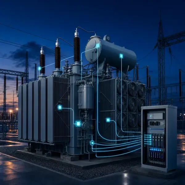
Share the transformer design, measurement points, installation stage and communication requirements. FUZHOUINNO will review a suitable product and monitoring configuration.