
Tap changer operating signatures
Transformer OLTC and Tap Changer Monitoring
Monitor tap changer switching time, motor current, vibration, position and compartment temperature for early fault warning.
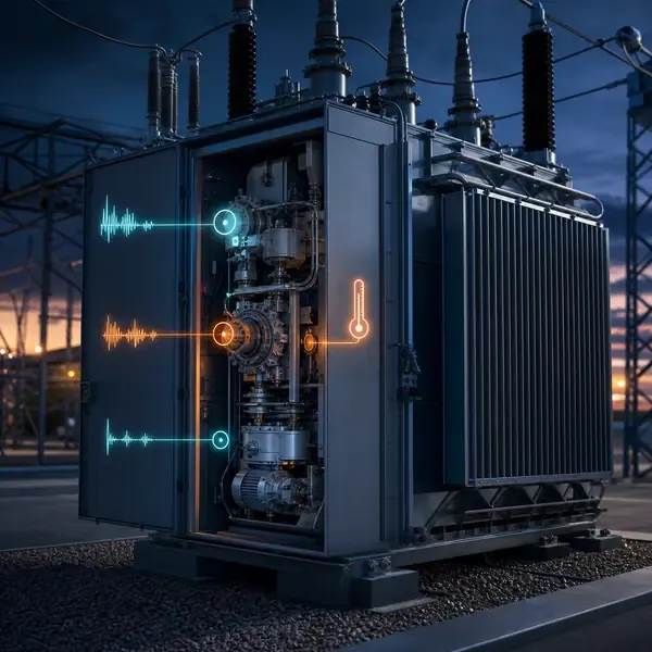
Monitoring scope
Transformer Parameters and Decision Inputs
- Drive-motor current signature
- Vibration signature
- Operation sequence and timing
- Compartment temperature
Why Is Transformer OLTC and Tap Changer Monitoring Needed?
transformer OLTC monitoring
An on-load tap changer performs mechanical and electrical switching while the transformer remains energized. Contact wear, drive resistance or timing errors may develop gradually and appear only during an operation.
Motor current, vibration, command, position, timing and compartment temperature are recorded as one synchronized event. Raise and lower operations and different tap steps need separate comparison groups.
What Does the System Measure?
Current, vibration, position, operation and temperature sensors are selected according to the tap changer mechanism and accessible signals.
OLTC monitoring triggers synchronized recording during each tap operation. Motor current, vibration, position contacts, operating time and compartment temperature are aligned by direction and step to reveal changes in drive effort and mechanical sequence.
| Signal | What it can reveal | Required comparison |
|---|---|---|
| Motor current | Drive effort, stalls and mechanical resistance | Same direction, step and supply condition |
| Vibration | Mechanical impact sequence and timing | Baseline from the same OLTC design |
| Position / timing | Incomplete or delayed sequence | Command, transition and final position |
| Temperature | Compartment or contact-heating context | Load, oil and recent operation history |
How Does the Equipment Work in the Field?
Acquisition is triggered by a tap operation so channels can be aligned by direction, step and sequence. Baseline signatures are stored for later comparison.
Motor current, vibration, command, position, timing and compartment temperature are recorded as one synchronized event. Raise and lower operations and different tap steps need separate comparison groups.
What Can an Abnormal Trend Look Like?
A longer motor-current travel time with a shifted vibration impact may indicate growing mechanical resistance. First rule out low motor supply voltage and compare the event with the same direction and tap transition.
Preserve the full event record rather than only an alarm bit. Review operation count, direction, step, supply voltage and recent OLTC maintenance before planning inspection.
How Is the System Installed and Commissioned?
Scope definition requires OLTC type, motor supply, control circuit, available contacts, sensor mounting locations, typical operation frequency and maintenance records.
Commissioning should prove each channel with a realistic input, confirm the channel name and units, simulate alarms and record the first usable baseline.
- Confirm motor supply and non-invasive current-sensor location
- Mount vibration sensors reproducibly
- Capture raise and lower baselines across representative steps
- Synchronize command, current, vibration and position channels
How Are Alarms and SCADA Data Used?
Rules should account for normal variation between raise and lower operations, load conditions and mechanism types. Persistent timing or effort changes deserve engineering review.
Operation count, last event status, summary indicators and alarms can be communicated to the broader transformer monitoring system.
Which Transformer Projects Are a Good Fit?
Suitable for frequently operated OLTCs, aging drive mechanisms and critical transformers where an unexpected tap-changer outage is costly.
Signature changes indicate altered behavior but do not identify every mechanical cause. Inspection and manufacturer maintenance procedures remain necessary.
What Should Buyers Confirm Before Ordering?
Compare proposals line by line. Confirm the included sensors, cables, field equipment, software, drawings, commissioning work and communication interface instead of comparing only the monitoring host.
- OLTC make, model and drive diagram
- Motor supply and accessible contacts
- Trigger logic, sampling rate and record length
- Baseline comparison and event-storage capacity
Transformer Monitoring Procurement Checklist
- Transformer type, rating and voltage class
- Priority failure modes and monitored points
- New-build or retrofit installation stage
- Required channels, alarms and communication protocols
- Drawings, cabinet, power and environmental requirements
Transformer OLTC and Tap Changer Monitoring Frequently Asked Questions
What is included in a transformer oltc and tap changer monitoring?
The final scope depends on transformer design and project objectives. It normally combines selected sensors, field acquisition, alarms, communications and an engineering response process.
Can this solution be installed on an existing transformer?
Retrofit feasibility depends on sensor access and outage constraints. External measurements are usually easier to retrofit than winding sensors installed inside the active part.
Can the system connect to SCADA?
Yes when the selected field equipment supports the required interface. The protocol, tag list, network responsibility and acceptance tests must be defined.
Does online monitoring replace offline testing?
No. Online trends reduce information gaps, while offline tests, oil samples and inspections remain important confirmation tools.
What should be provided for a technical proposal?
Provide transformer drawings and ratings, installation stage, required measurements, communication architecture, alarm philosophy and project quantity.
Related Products, Applications and Guides
- Transformer monitoring products
- Relevant transformer monitoring application
- Transformer OLTC monitoring guide
- All transformer monitoring solutions
- Integrated transformer monitoring system
Monitoring guidance is provided for project scoping. Final sensor placement, alarm settings, interfaces and diagnostic actions depend on transformer design and owner procedures.
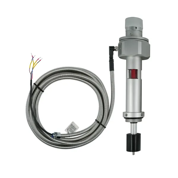
Project-ready supportProduct selectionSensors and instruments matched to the required measurement. System integrationChannels, alarms and communication interfaces defined for the project. Technical documentsSpecifications and available order documentation confirmed before supply.
Transformer monitoring built around your equipment
Share the transformer design, measurement points, installation stage and communication requirements. FUZHOUINNO will review a suitable product and monitoring configuration.
Start a technical discussion