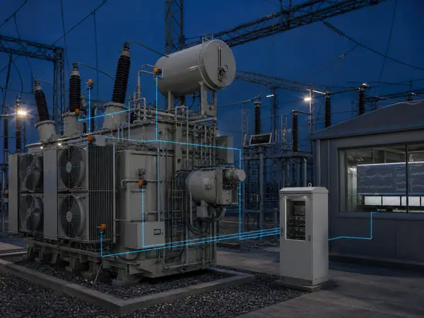
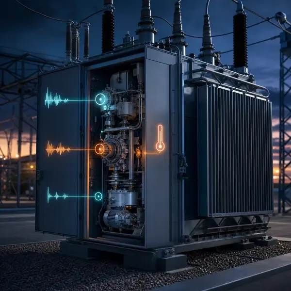
1. What Does an OLTC Monitoring System Observe?
An on-load tap changer performs mechanical and electrical switching while the transformer remains energized. Contact wear, drive resistance or timing errors may develop gradually and appear only during an operation. This matters to transformer maintenance engineers, utilities and industrial operators.
Start by naming the transformer component, the expected fault or operating change, and the decision the measurements must support. The scope for transformer on-load tap changer monitoring must remain tied to that purpose.
Motor current, vibration, command, position, timing and compartment temperature are recorded as one synchronized event. Raise and lower operations and different tap steps need separate comparison groups. The measurement path must remain traceable from sensor to alarm.
Useful evidence comes from motor current, vibration or acoustic signature and operation time. These measurements should help the owner compare repeatable operating signatures and identify changes that justify focused maintenance.
A good result is not another dashboard value. It is a clear answer about which operations form the baseline, supported by measurements that the maintenance team can check.
An OLTC monitoring system records what happens during each tap change rather than relying only on operation count. Useful records align the command, tap direction, motor current, mechanical vibration, transition time, final position and relevant compartment conditions.
2. How Raise and Lower Operations Create Different Baselines
An actionable alarm separates absolute level, rate of change, persistence and instrument health. The setting must identify an owner and response; otherwise a threshold creates a notification but no maintenance decision.
Motor current, vibration, command, position, timing and compartment temperature are recorded as one synchronized event. Raise and lower operations and different tap steps need separate comparison groups. Record where each value originates and which operating condition can change it.
Vibration: mechanical impact sequence and timing. Verification point: Baseline from the same OLTC design. Keep the channel identity, units, timestamp and instrument status with the result.
Using one signature without load context can make a correct instrument look misleading. Check the measurement method and the transformer state before assigning a fault.
Raise and lower operations often have different normal signatures. Tap position, direction, oil temperature and motor supply also influence the event, so the baseline should group comparable operations instead of combining every trace into one average.
3. What Motor-Current Shape Reveals About Drive Effort
The available measurements observe different parts of transformer on-load tap changer monitoring. No single value should be treated as a complete diagnosis.
Position / timing: incomplete or delayed sequence. Verification point: Command, transition and final position. Keep the channel identity, units, timestamp and instrument status with the result.
Review operation time together with tap position. Their direction, timing and persistence help separate a transformer change from normal operation or a sensor problem.
For operation time, document the physical point, range, sampling behavior and expected output. This makes commissioning and later troubleshooting much easier.
Motor current shows starting demand, drive effort, travel duration and stopping behavior. A longer or higher-current event can indicate increased resistance, but low supply voltage and control timing must be ruled out before mechanical work is scheduled.
| Signal | What it can reveal | Required comparison |
|---|---|---|
| Motor current | Drive effort, stalls and mechanical resistance | Same direction, step and supply condition |
| Vibration | Mechanical impact sequence and timing | Baseline from the same OLTC design |
| Position / timing | Incomplete or delayed sequence | Command, transition and final position |
| Temperature | Compartment or contact-heating context | Load, oil and recent operation history |
4. How Vibration and Timing Describe the Mechanical Sequence
An OLTC event is evaluated as a synchronized sequence: command, motor-current start and travel, vibration impacts, transition timing and final position. Raise and lower operations, different tap steps and motor-supply variation require separate baselines.
The signal path for tap position runs from the sensing point through cables, optical leads or an oil loop to the acquisition unit. Local processing stores the record and sends selected values or alarms onward.
Temperature: compartment or contact-heating context. Verification point: Load, oil and recent operation history. Keep the channel identity, units, timestamp and instrument status with the result.
Sampling and storage for temperature and oil condition must match the physical event. Slow oil movement, a brief OLTC operation and a high-frequency PD pulse need different acquisition settings.
Vibration captures impacts produced by the drive and switching sequence. Stable sensor mounting and synchronized acquisition are essential; a moved accelerometer can change amplitude enough to resemble a developing mechanical fault.
Compare available transformer monitoring products and instruments after the sensor locations, channel quantity and required outputs are known.
5. How Position Contacts and Operation Count Add Context
Field example: A longer motor-current travel time with a shifted vibration impact may indicate growing mechanical resistance. First rule out low motor supply voltage and compare the event with the same direction and tap transition.
Temperature and oil condition alone does not explain the result. Motor current provides the comparison needed to test the first explanation.
Preserve the full event record rather than only an alarm bit. Review operation count, direction, step, supply voltage and recent OLTC maintenance before planning inspection.
This evidence helps determine which operations form the baseline. Depending on severity and confidence, the next step may be continued trending, inspection, a controlled sample or an offline test.
Position contacts and operation count explain where the mechanism started and whether it reached the commanded tap. They help identify incomplete or delayed sequences but do not show contact wear by themselves.
6. How Compartment Temperature and Oil Condition Support Diagnosis
A useful baseline for motor current is recorded under known transformer conditions. A value without load, temperature, cooling or maintenance history is difficult to compare.
Review motor current together with vibration or acoustic signature. Their direction, timing and persistence help separate a transformer change from normal operation or a sensor problem.
Vibration: mechanical impact sequence and timing. Verification point: Baseline from the same OLTC design. Keep the channel identity, units, timestamp and instrument status with the result.
After sensor replacement, oil processing or a configuration change, mark a new comparison period for motor current. Otherwise maintenance may look like sudden deterioration or recovery.
Compartment temperature and oil condition add context about repeated operations, contact heating and local insulation. These slower trends should be reviewed beside event signatures rather than treated as substitutes for current or vibration capture.
7. How to Compare Events Without Creating False Alarms
An actionable alarm separates absolute level, rate of change, persistence and instrument health. The setting must identify an owner and response; otherwise a threshold creates a notification but no maintenance decision.
Ignoring mechanism and diverter design is a significant interpretation risk for vibration or acoustic signature. Preserve the original reading and compare it with an independent observation before escalating.
Preserve the full event record rather than only an alarm bit. Review operation count, direction, step, supply voltage and recent OLTC maintenance before planning inspection.
This evidence helps determine which changes require inspection. Depending on severity and confidence, the next step may be continued trending, inspection, a controlled sample or an offline test.
Comparison rules should use like-for-like events and retain representative raw traces. A persistent change in timing, missing vibration impact or increased drive effort should prompt review of supply, mechanism history and inspection needs.
- Mixing different tap operations — check the sensor, operating state and related measurements before assigning a transformer fault.
- Using one signature without load context — check the sensor, operating state and related measurements before assigning a transformer fault.
- Ignoring mechanism and diverter design — check the sensor, operating state and related measurements before assigning a transformer fault.
- Failing to capture post-maintenance baselines — check the sensor, operating state and related measurements before assigning a transformer fault.
8. Which OLTC Signals Are Available on Your Tap Changer?
Compare oltc make, model and drive diagram and motor supply and accessible contacts before comparing price. Two proposals are not equivalent when one includes field sensors, cables, drawings and commissioning while the other lists only the monitor.
The proposal for transformer on-load tap changer monitoring should tie motor current to a model, measurement point, stated performance basis and included installation parts. This makes price differences explainable.
Installation and testing cannot remain an undefined site task. Assign responsibility for confirm motor supply and non-invasive current-sensor location and final review of which operations form the baseline.
Approve equipment release only after the bill of materials, channel list, drawings, alarm behavior, tests and documents are complete. Acceptance for motor current must demonstrate the specified readings and interfaces.
Begin with the OLTC make, model, drive arrangement and accessible signals. Operation count alone is insufficient when the project objective is to compare mechanical sequence, drive effort or switching behavior.
Review the related transformer monitoring solution before selecting instruments for motor current.
9. What Sampling, Trigger and Event Storage Should Be Quoted?
Send the nameplate, general arrangement, installation stage and available drawings with the inquiry. Mark the locations related to motor current and vibration or acoustic signature and identify existing instruments that may be reused.
Ask how the offered equipment handles vibration or acoustic signature: where it is measured, how often it is recorded, which alarm uses it and what appears in the delivered test report.
Assign responsibility for mount vibration sensors reproducibly, approval of how direction and tap step are separated, and final acceptance.
Before production, freeze the options that affect vibration or acoustic signature. The order should list tests, configuration files, documentation language, commissioning records and support responsibilities.
Specify current sensors, vibration mounting, position inputs, trigger rules, event sampling, synchronized storage, temperature channels and comparison by direction and tap step.
| Proposal item | What the buyer should verify | Why it changes the comparison |
|---|---|---|
| OLTC make, model and drive diagram | Included model, quantity, performance basis and responsibility | Prevents unlike hardware scopes from appearing equivalent |
| Motor supply and accessible contacts | Drawing, interface, test method and delivered record | Prevents installation and commissioning work from becoming an unpriced change |
| Trigger logic, sampling rate and record length | Included model, quantity, performance basis and responsibility | Prevents unlike hardware scopes from appearing equivalent |
| Baseline comparison and event-storage capacity | Drawing, interface, test method and delivered record | Prevents installation and commissioning work from becoming an unpriced change |
10. What OLTC Drawings and Operation Records Should Buyers Send?
Suitable for frequently operated OLTCs, aging drive mechanisms and critical transformers where an unexpected tap-changer outage is costly. Start with the transformer, the problem to be detected and the action expected after an alarm. The scope must clarify which changes require inspection.
For operation time, require the exact model, quantity, range, accessories, outputs and communication interface. Optional work should be separated from the base supply.
Split field responsibilities before ordering transformer on-load tap changer monitoring. The quotation should assign responsibility for capture raise and lower baselines across representative steps and approval of which changes require inspection.
The purchase record for transformer on-load tap changer monitoring should show what arrives on site and how it will be checked. Do not replace measurable acceptance criteria with a promise to predict every failure.
Provide drive schematics, motor supply, position-contact details, operation records, maintenance dates and available mounting locations. Capture a new baseline after overhaul or mechanism adjustment.
- OLTC make, model and drive diagram
- Motor supply and accessible contacts
- Trigger logic, sampling rate and record length
- Baseline comparison and event-storage capacity
- Transformer details relevant to motor current, vibration or acoustic signature and operation time
- Approved channel list, interfaces, tests and documentation