1. Understanding a Transformer Monitoring System
A transformer can pass a scheduled inspection and still develop overheating, gas generation or insulation activity before the next visit. Separate gauges make the problem harder because no one sees the measurements on the same timeline. This matters to asset owners, EPC engineers, transformer OEM teams and technical buyers.
Start by naming the transformer component, the expected fault or operating change, and the decision the measurements must support. The scope for selection of a transformer monitoring system must remain tied to that purpose.
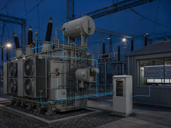
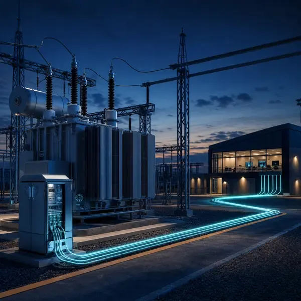
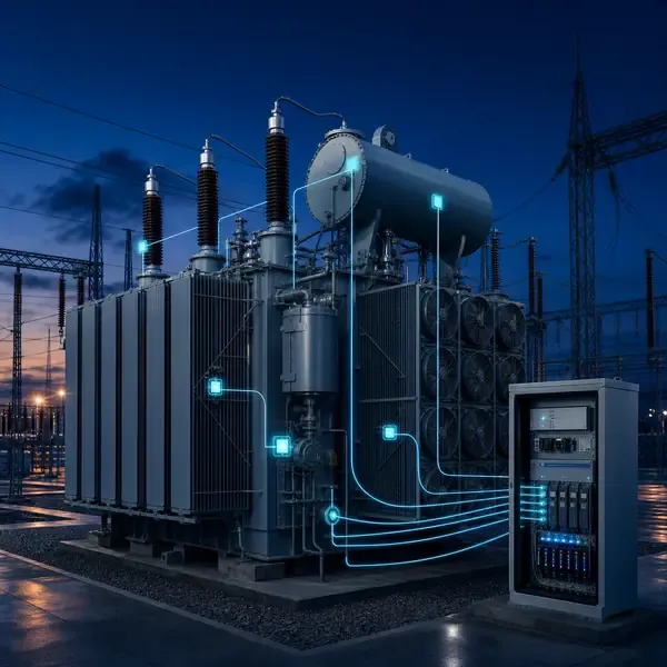
An online system brings selected temperature, oil, gas, discharge and mechanical signals into field acquisition equipment. Each channel keeps its own sampling method, device status and history while the control room receives a smaller set of alarms and operating values. The measurement path must remain traceable from sensor to alarm.
Useful evidence comes from asset criticality, credible failure modes and available sensor points. These measurements should help the owner translate asset risk and operational response into a clear, comparable procurement specification.
A good result is not another dashboard value. It is a clear answer about online versus periodic coverage, supported by measurements that the maintenance team can check.
Begin with an asset worksheet rather than a product brochure. Record transformer type, voltage and power rating, cooling class, duty, redundancy, age, known defects, outage consequence and the maintenance action available after an alarm. These facts determine whether continuous monitoring adds operational value.
2. Transformer Conditions That Can Be Monitored
Transformer construction and the required decision determine the suitable method. Relevant inputs include asset criticality, credible failure modes, available sensor points and required communication protocols.
An online system brings selected temperature, oil, gas, discharge and mechanical signals into field acquisition equipment. Each channel keeps its own sampling method, device status and history while the control room receives a smaller set of alarms and operating values. Record where each value originates and which operating condition can change it.
Field acquisition: conditions, timestamps and stores the signal. Verification point: Channel map, clock check and retained history. Keep the channel identity, units, timestamp and instrument status with the result.
Using vague accuracy language can make a correct instrument look misleading. Check the measurement method and the transformer state before assigning a fault.
Separate observable conditions from broad claims about health. Temperature channels can reveal thermal behavior, DGA follows oil and paper decomposition, partial-discharge instruments capture discharge-related activity, and oil-level or pressure devices report containment conditions. None of these measurements covers every failure mechanism.
3. Temperature, DGA, Partial Discharge and Oil Monitoring Compared
Temperature reveals thermal stress, DGA follows chemical decomposition in oil and paper, partial-discharge monitoring captures localized electrical activity, and oil sensors follow moisture, level, pressure and bulk thermal condition. These methods overlap in fault coverage but do not measure the same physical phenomenon.
Alarm layer: applies threshold, persistence and device-health rules. Verification point: Simulated advisory, warning and sensor-fault events. Keep the channel identity, units, timestamp and instrument status with the result.
Review available sensor points together with required communication protocols. Their direction, timing and persistence help separate a transformer change from normal operation or a sensor problem.
For available sensor points, document the physical point, range, sampling behavior and expected output. This makes commissioning and later troubleshooting much easier.
Choose complementary methods only when the team can interpret and act on them. A large multi-gas analyzer may be justified on a critical generator step-up transformer, while a smaller industrial unit may gain more from reliable winding temperature, cooling feedback and oil-condition alarms.
| Monitoring layer | Concrete function | Acceptance evidence |
|---|---|---|
| Sensor layer | Measures a defined physical parameter at a named location | Drawing, sensor ID, range and realistic reading |
| Field acquisition | Conditions, timestamps and stores the signal | Channel map, clock check and retained history |
| Alarm layer | Applies threshold, persistence and device-health rules | Simulated advisory, warning and sensor-fault events |
| Station interface | Publishes selected values, quality and status | Approved tag list and communication-loss test |
4. Online Monitoring vs Periodic Testing
Online monitoring records behavior between inspections and can raise a remote alarm; periodic testing provides a controlled snapshot and often higher diagnostic detail. A sound program uses the online trend to decide when inspection, laboratory sampling or an offline electrical test is justified.
The signal path for required communication protocols runs from the sensing point through cables, optical leads or an oil loop to the acquisition unit. Local processing stores the record and sends selected values or alarms onward.
Station interface: publishes selected values, quality and status. Verification point: Approved tag list and communication-loss test. Keep the channel identity, units, timestamp and instrument status with the result.
Sampling and storage for maintenance response capability must match the physical event. Slow oil movement, a brief OLTC operation and a high-frequency PD pulse need different acquisition settings.
Periodic inspection remains suitable for slow, visible or low-consequence changes. Continuous measurement becomes more valuable when a fault can develop between visits, the transformer is remote, loading changes quickly or an unplanned outage has a high consequence.
Compare available transformer monitoring products and instruments after the sensor locations, channel quantity and required outputs are known.
5. Matching Monitoring Methods to Transformer Failure Risks
Field example: A rising top-oil temperature is not automatically a cooling fault. If load is rising and the next fan stage starts normally, the response may be expected. If temperature continues to climb after the fan command, current feedback and stage status should be checked before the operator increases loading.
Maintenance response capability alone does not explain the result. Asset criticality provides the comparison needed to test the first explanation.
Check the affected channel, compare related measurements and confirm the operating state. The alarm procedure should then name the inspection, oil sample or offline test required for escalation.
This evidence helps determine online versus periodic coverage. Depending on severity and confidence, the next step may be continued trending, inspection, a controlled sample or an offline test.
Write one line for each credible failure risk: the physical change, the sensor that can observe it, the alarm condition, the person who receives it and the confirmation step. Any channel that cannot complete that chain needs a clearer purpose before it is purchased.
6. How Many Sensors and Monitoring Channels Are Needed?
Channel count comes from named physical points, not transformer MVA alone. A three-phase winding scheme may need multiple probes per phase, while PD localization needs synchronized sensors at separated positions and DGA normally uses gas channels inside one oil-analysis instrument.
Review asset criticality together with credible failure modes. Their direction, timing and persistence help separate a transformer change from normal operation or a sensor problem.
Field acquisition: conditions, timestamps and stores the signal. Verification point: Channel map, clock check and retained history. Keep the channel identity, units, timestamp and instrument status with the result.
After sensor replacement, oil processing or a configuration change, mark a new comparison period for asset criticality. Otherwise maintenance may look like sudden deterioration or recovery.
Count actual measurement locations on drawings. Identify phases, windings, oil points, bushing references, grounding paths and tap-changer signals; then add only the spare capacity that has a named future use. Monitor input count alone does not prove that the required sensors and accessories are included.
7. New Transformer Installation vs Retrofit Monitoring
New transformers can receive winding probes, feedthroughs and internal lead routing before tank closure. Retrofit projects usually depend on existing oil valves, test taps, grounding conductors, thermometer pockets, tank surfaces and available cable routes; an internal hot-spot probe cannot normally be added without major active-part work.
Omitting commissioning deliverables is a significant interpretation risk for credible failure modes. Preserve the original reading and compare it with an independent observation before escalating.
Check the affected channel, compare related measurements and confirm the operating state. The alarm procedure should then name the inspection, oil sample or offline test required for escalation.
This evidence helps determine channel count and expansion. Depending on severity and confidence, the next step may be continued trending, inspection, a controlled sample or an offline test.
New transformers allow internal probes, feedthroughs and cable routes to be coordinated during design and manufacture. Retrofit selection starts with accessible valves, pockets, test taps, grounding conductors, panel space and outage limits. Treat these as different engineering scopes even when the displayed parameters appear similar.
- Specifying a brand-style package without functional requirements — check the sensor, operating state and related measurements before assigning a transformer fault.
- Using vague accuracy language — check the sensor, operating state and related measurements before assigning a transformer fault.
- Omitting commissioning deliverables — check the sensor, operating state and related measurements before assigning a transformer fault.
- Failing to define alarm responsibility — check the sensor, operating state and related measurements before assigning a transformer fault.
8. Choosing a System for the Transformer Application
Send the nameplate, general arrangement, installation stage and available drawings with the inquiry. Mark the locations related to asset criticality and credible failure modes and identify existing instruments that may be reused.
Ask how the offered equipment handles asset criticality: where it is measured, how often it is recorded, which alarm uses it and what appears in the delivered test report.
Assign responsibility for map every channel to a transformer drawing and failure mode, approval of online versus periodic coverage, and final acceptance.
Before production, freeze the options that affect asset criticality. The order should list tests, configuration files, documentation language, commissioning records and support responsibilities.
A selection matrix should compare asset consequence, failure risk, available access, response time and confirmation method. Use the matrix to remove channels that have no practical response, not to force every transformer into the same package.
Review the related transformer monitoring solution before selecting instruments for asset criticality.
9. Supplier Proposal Requirements
Best suited to critical, remote or heavily loaded transformers where a developing condition must be seen between routine inspections. Start with the transformer, the problem to be detected and the action expected after an alarm. The scope must clarify factory installation versus retrofit.
For credible failure modes, require the exact model, quantity, range, accessories, outputs and communication interface. Optional work should be separated from the base supply.
Split field responsibilities before ordering selection of a transformer monitoring system. The quotation should assign responsibility for separate signal, power and communication routing as required and approval of factory installation versus retrofit.
The purchase record for selection of a transformer monitoring system should show what arrives on site and how it will be checked. Do not replace measurable acceptance criteria with a promise to predict every failure.
Normalize quotations before comparing price. Put sensor quantity, monitor inputs, cables, feedthroughs, cabinets, software, protocols, drawings, factory tests, site work and commissioning on separate rows so exclusions are visible.
| Proposal item | What the buyer should verify | Why it changes the comparison |
|---|---|---|
| Channel schedule and spare capacity | Included model, quantity, performance basis and responsibility | Prevents unlike hardware scopes from appearing equivalent |
| Sampling and local storage by signal type | Drawing, interface, test method and delivered record | Prevents installation and commissioning work from becoming an unpriced change |
| Protocol, timestamps, quality flags and tag ownership | Included model, quantity, performance basis and responsibility | Prevents unlike hardware scopes from appearing equivalent |
| Cabinet power, environment and cybersecurity boundary | Drawing, interface, test method and delivered record | Prevents installation and commissioning work from becoming an unpriced change |
10. What Project Information Should You Send for a Quote?
Compare protocol, timestamps, quality flags and tag ownership and cabinet power, environment and cybersecurity boundary before comparing price. Two proposals are not equivalent when one includes field sensors, cables, drawings and commissioning while the other lists only the monitor.
The proposal for selection of a transformer monitoring system should tie available sensor points to a model, measurement point, stated performance basis and included installation parts. This makes price differences explainable.
Installation and testing cannot remain an undefined site task. Assign responsibility for retain local data during station-network interruption and final review of channel count and expansion.
Approve equipment release only after the bill of materials, channel list, drawings, alarm behavior, tests and documents are complete. Acceptance for available sensor points must demonstrate the specified readings and interfaces.
Useful inquiry drawings include the nameplate, general arrangement, control schematic, oil-valve layout and existing instrument list. Mark intended sensor points and identify whether installation will occur during manufacture, a planned outage or energized service.
- Channel schedule and spare capacity
- Sampling and local storage by signal type
- Protocol, timestamps, quality flags and tag ownership
- Cabinet power, environment and cybersecurity boundary
- Transformer details relevant to asset criticality, credible failure modes and available sensor points
- Approved channel list, interfaces, tests and documentation