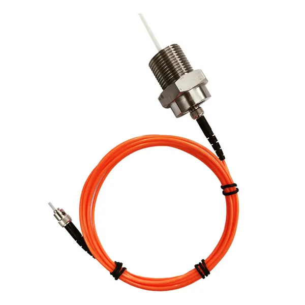
transformer fiber optic temperature sensor
Armored Fiber Optic Temperature Sensor for Oil-Immersed Transformer Windings
Armored fluorescent fiber optic sensing for direct winding hot-spot temperature measurement in oil-immersed power transformers.

Measure selected transformer winding hot spots with direct probes, thermal context and multi-channel temperature acquisition.
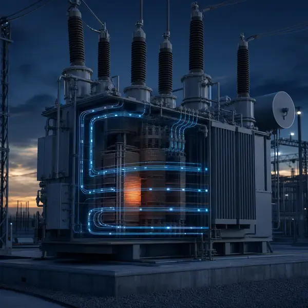
Compare available sensors and instruments that can support this project scope.
Armored fluorescent fiber optic sensing for direct winding hot-spot temperature measurement in oil-immersed power transformers.
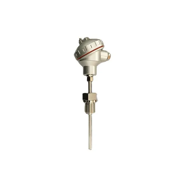
PT100 resistance temperature sensor for transformer oil and accessible thermal monitoring points.
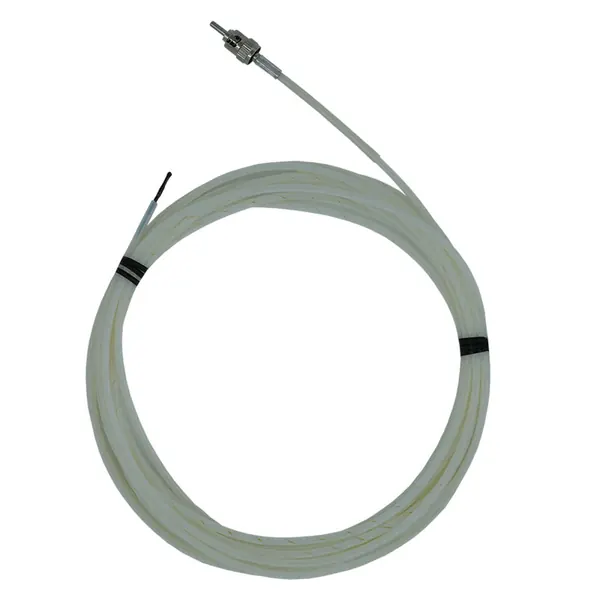
Dielectric winding-tube sensor for direct transformer hot-spot measurement in strong electromagnetic fields.
transformer hot spot monitoring
The hottest part of a winding is rarely the same as the average winding or top-oil temperature. Repeated operation above the intended thermal profile accelerates cellulose aging at that local point.
The transformer designer identifies likely hot regions from winding geometry and thermal calculation. Multiple embedded probes then verify selected axial, radial and phase locations during test and service.
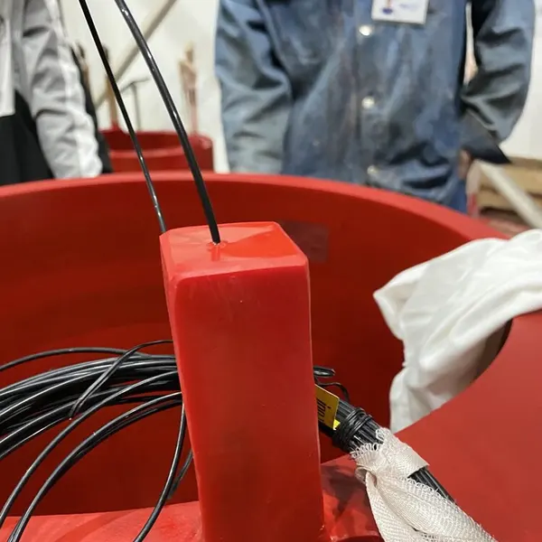
Armored fluorescent fiber optic probes can be positioned at modelled hot spot regions during transformer manufacture. Multiple points help distinguish a local anomaly from a general load-related rise.
A hot-spot system places multiple fluorescent fiber-optic probes near thermally modeled conductor regions and measures temperature from fluorescence decay time. Direct readings are compared with load, top-oil, bottom-oil, ambient and cooling state. One probe represents one local point, not the entire winding.
| Design input | Why it matters | Required record |
|---|---|---|
| Thermal design model | Identifies credible axial and radial hot regions | Probe-location drawing and hot-spot factor assumptions |
| Fluorescence decay probe | Direct dielectric point measurement inside the winding | Sensor construction, response and channel verification |
| Multiple probes | Distinguishes local heating from general temperature rise | Phase, LV/HV/tertiary and physical-location channel map |
| WTI / top-oil reference | Provides indirect thermal reference | CT, heater, thermometer-pocket and cooling configuration |
| Temperature-rise test | Checks measured response against design expectations | Load, ambient, top/bottom oil, cooling and channel trend |
Each optical probe connects through an approved feedthrough and extension path to a matched demodulation instrument. Channel naming must preserve the physical winding and axial or radial location.
The transformer designer identifies likely hot regions from winding geometry and thermal calculation. Multiple embedded probes then verify selected axial, radial and phase locations during test and service.
A hot-spot probe that rises faster after a pump change may reveal restricted local oil flow. The useful comparison is not one absolute value; it is the temperature rise above top oil, the phase-to-phase spread and the response before and after cooling starts.
Compare probe temperature with load, ambient, top oil and cooling stage. Escalate a persistent phase or location difference that cannot be explained by the approved thermal design.
The transformer designer should confirm probe placement, mechanical protection, bending radius, fluid compatibility and lead routing before the winding is completed.
Commissioning should prove each channel with a realistic input, confirm the channel name and units, simulate alarms and record the first usable baseline.
Alarm settings should be based on the measurement objective and transformer thermal design rather than copied from a different sensor location. Rate and persistence can be as important as the absolute value.
Hot spot values can support SCADA display, transformer thermal models and engineering trend review. High-resolution commissioning data may be retained separately from routine operational tags.
Most valuable for new power transformers, high-loading applications, prototype validation and OEM temperature-rise tests.
Direct measurement improves certainty at instrumented points but cannot measure every conductor location. Placement quality and the number of probes determine how representative the data will be.
Compare proposals line by line. Confirm the included sensors, cables, field equipment, software, drawings, commissioning work and communication interface instead of comparing only the monitoring host.
The final scope depends on transformer design and project objectives. It normally combines selected sensors, field acquisition, alarms, communications and an engineering response process.
Retrofit feasibility depends on sensor access and outage constraints. External measurements are usually easier to retrofit than winding sensors installed inside the active part.
Yes when the selected field equipment supports the required interface. The protocol, tag list, network responsibility and acceptance tests must be defined.
No. Online trends reduce information gaps, while offline tests, oil samples and inspections remain important confirmation tools.
Provide transformer drawings and ratings, installation stage, required measurements, communication architecture, alarm philosophy and project quantity.
Monitoring guidance is provided for project scoping. Final sensor placement, alarm settings, interfaces and diagnostic actions depend on transformer design and owner procedures.
Share the transformer design, measurement points, installation stage and communication requirements. FUZHOUINNO will review a suitable product and monitoring configuration.