
Capacitance and leakage-current trends
Transformer Bushing Condition Monitoring
Monitor transformer bushing insulation condition through capacitance, dielectric loss, leakage current, temperature and comparative trends.
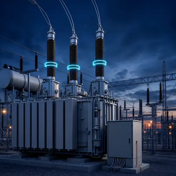
Monitoring scope
Transformer Parameters and Decision Inputs
- Leakage current
- Capacitance change
- Dielectric-loss trend
- Phase or reference comparison
Why Is Transformer Bushing Condition Monitoring Needed?
transformer bushing monitoring
A condenser bushing can deteriorate internally while the main transformer remains electrically normal. Moisture, grading-layer damage and terminal resistance can lead to dielectric failure or local heating.
Online systems may compare test-tap leakage current, apparent capacitance, dielectric-loss trend, terminal temperature and bushing-origin discharge. The reference method must account for phase voltage, temperature and weather.
What Does the System Measure?
Monitoring uses compatible bushing test taps or other approved interfaces. Sensor and adapter selection must preserve the bushing manufacturer’s grounding and safety requirements.
Bushing monitoring combines electrical, thermal and partial-discharge evidence. Approved C2/test-tap interfaces support leakage-current, apparent-capacitance and dielectric-loss trending; terminal and flange temperature reveal contact or localized heating; UHF or acoustic channels can detect discharge activity. Tap grounding and overvoltage protection remain safety-critical.
| Indicator | Useful comparison | Major influence |
|---|---|---|
| C2/test-tap current | Same bushing over time and phase reference | System voltage, load, temperature and surface contamination |
| Capacitance / tan delta trend | Stable baseline and phase comparison | Tap adapter, reference and measurement-chain stability |
| Terminal / flange temperature | Load-normalized comparison among bushings | Clamp resistance, eddy heating and accessible surface only |
| UHF / acoustic PD | Repeatable discharge activity near the bushing root | Interference, PRPD pattern and sensor geometry |
| Infrared survey | External clamp and porcelain surface temperature snapshot | Cannot observe internal condenser heating between surveys |
How Does the Equipment Work in the Field?
Tap signals feed protected acquisition channels that calculate comparative indicators and monitor sensor integrity. The reference method must remain stable across operating conditions.
Online systems may compare test-tap leakage current, apparent capacitance, dielectric-loss trend, terminal temperature and bushing-origin discharge. The reference method must account for phase voltage, temperature and weather.
What Can an Abnormal Trend Look Like?
A gradual divergence in one phase is more useful than a single fleet-wide threshold. If capacitance trend and terminal temperature both change on the same bushing, inspect the connection and confirm with the owner’s approved offline bushing tests.
Verify test-tap protection and grounding before interpreting data. Compare like bushings, check voltage and weather effects, and retain the original current or phase records.
How Is the System Installed and Commissioned?
The buyer must provide bushing type, voltage class, tap details, phase arrangement, drawings, station grounding information and desired alarm integration.
Commissioning should prove each channel with a realistic input, confirm the channel name and units, simulate alarms and record the first usable baseline.
- Identify OIP, RIP or other bushing construction and obtain maker/test-tap drawings
- Use an adapter that maintains required tap protection and grounding
- Document phase reference, station grounding, grading-ring and terminal-clamp arrangement
- Baseline temperature, leakage current and PD under comparable load and weather
- Verify safe tap grounding after monitor disconnection
How Are Alarms and SCADA Data Used?
Alarms should use persistence and comparison rather than a single instantaneous threshold. Sudden simultaneous changes may indicate a system or reference disturbance.
Selected trends, deviations and equipment-status alarms can enter station systems, while detailed phase comparisons remain available for specialist review.
Which Transformer Projects Are a Good Fit?
Permanent monitoring is most relevant to high-voltage bushings, critical transformers and units with suspect test history or limited outage access.
Online trends support early assessment but do not replace capacitance, power-factor or dielectric testing performed with appropriate offline procedures.
What Should Buyers Confirm Before Ordering?
Compare proposals line by line. Confirm the included sensors, cables, field equipment, software, drawings, commissioning work and communication interface instead of comparing only the monitoring host.
- OIP/RIP bushing type and C2/test-tap compatibility
- Voltage class, phase arrangement and grounding method
- Leakage-current, capacitance/tan-delta and temperature reference method
- UHF/acoustic bandwidth, PRPD retention and localization objective
- Tap protection, fail-safe grounding and offline confirmation plan
Transformer Monitoring Procurement Checklist
- Transformer type, rating and voltage class
- Priority failure modes and monitored points
- New-build or retrofit installation stage
- Required channels, alarms and communication protocols
- Drawings, cabinet, power and environmental requirements
Transformer Bushing Condition Monitoring Frequently Asked Questions
What is included in a transformer bushing condition monitoring?
The final scope depends on transformer design and project objectives. It normally combines selected sensors, field acquisition, alarms, communications and an engineering response process.
Can this solution be installed on an existing transformer?
Retrofit feasibility depends on sensor access and outage constraints. External measurements are usually easier to retrofit than winding sensors installed inside the active part.
Can the system connect to SCADA?
Yes when the selected field equipment supports the required interface. The protocol, tag list, network responsibility and acceptance tests must be defined.
Does online monitoring replace offline testing?
No. Online trends reduce information gaps, while offline tests, oil samples and inspections remain important confirmation tools.
What should be provided for a technical proposal?
Provide transformer drawings and ratings, installation stage, required measurements, communication architecture, alarm philosophy and project quantity.
Related Products, Applications and Guides
- Transformer monitoring products
- Relevant transformer monitoring application
- Transformer bushing monitoring guide
- All transformer monitoring solutions
- Integrated transformer monitoring system
Monitoring guidance is provided for project scoping. Final sensor placement, alarm settings, interfaces and diagnostic actions depend on transformer design and owner procedures.
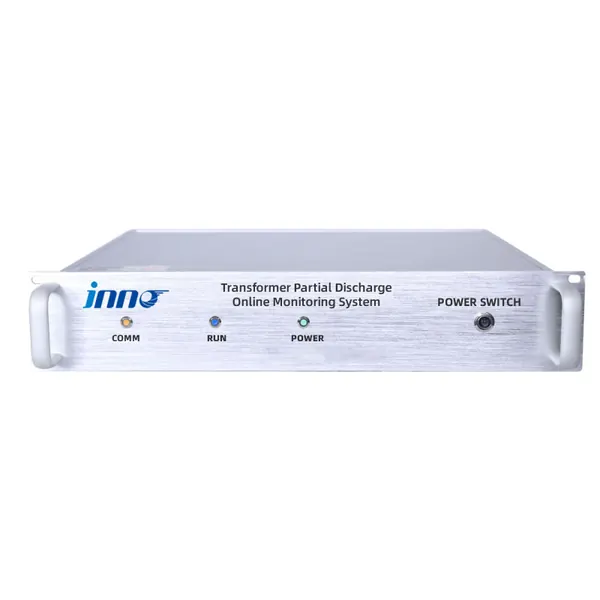
Project-ready supportProduct selectionSensors and instruments matched to the required measurement. System integrationChannels, alarms and communication interfaces defined for the project. Technical documentsSpecifications and available order documentation confirmed before supply.
Transformer monitoring built around your equipment
Share the transformer design, measurement points, installation stage and communication requirements. FUZHOUINNO will review a suitable product and monitoring configuration.
Start a technical discussion