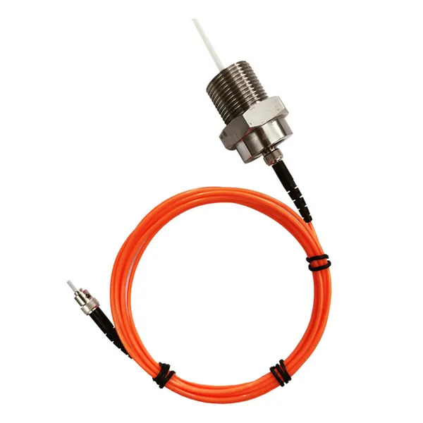
transformer fiber optic temperature sensor
Armored Fiber Optic Temperature Sensor for Oil-Immersed Transformer Windings
Armored fluorescent fiber optic sensing for direct winding hot-spot temperature measurement in oil-immersed power transformers.

Measure transformer winding temperature with fiber optic probes, RTDs, indicators and project-configured monitoring instruments.
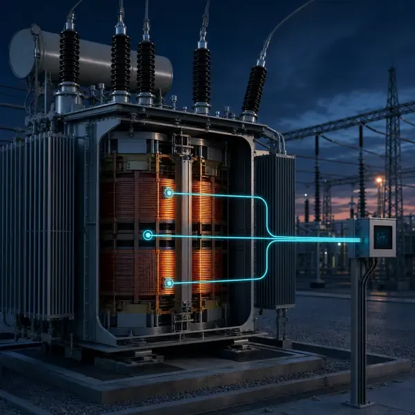
Compare available sensors and instruments that can support this project scope.
Armored fluorescent fiber optic sensing for direct winding hot-spot temperature measurement in oil-immersed power transformers.
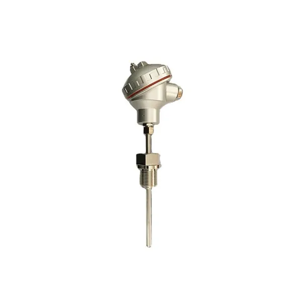
PT100 resistance temperature sensor for transformer oil and accessible thermal monitoring points.
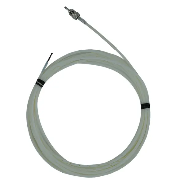
Dielectric winding-tube sensor for direct transformer hot-spot measurement in strong electromagnetic fields.
transformer winding temperature monitoring solution
Top-oil temperature can remain acceptable while one winding region runs hotter because of conductor geometry, uneven cooling or phase loading. That local temperature drives insulation aging but may not appear on a tank-mounted gauge.
Embedded fluorescent fiber-optic probes measure selected conductor regions directly. WTI instruments estimate winding temperature from oil temperature and load current. These methods complement each other, but they do not measure the same point.
Fluorescent fiber optic probes provide dielectric direct sensing for selected winding locations. PT100 inputs and conventional indicators remain practical for accessible points and many dry-type transformer designs.
Direct winding temperature uses dielectric fluorescent fiber-optic probes embedded at selected conductor locations. A pulsed optical signal excites the sensing tip and the temperature-dependent fluorescence decay time is converted to temperature. Indirect systems use top-oil temperature, load current and a thermal model or winding-temperature indicator; the two methods answer different questions.
| Method | Best use | Critical limitation |
|---|---|---|
| Embedded fiber-optic probe | Direct conductor-region temperature during test and service | Must be positioned and protected during winding manufacture |
| OTI / oil thermometer | Direct temperature from a bulb in a thermometer pocket | Represents local bulk oil, not winding hot spot |
| WTI thermal image | Simulated winding temperature using oil temperature plus CT-heated compensation | Accuracy depends on CT ratio, heater setting, thermal constants and cooling state |
| RTD or PT100 | Accessible dry-type winding, enclosure or oil-system points | Metallic sensor suitability depends on electrical location |
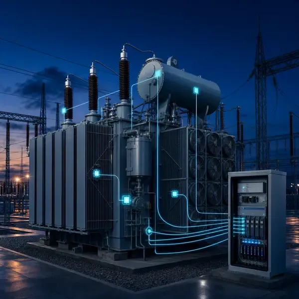
Embedded or accessible sensors route through compatible feedthroughs and cables to a multi-channel monitor. The monitor provides display, alarm, relay, analog or communication outputs according to the selected model.
Embedded fluorescent fiber-optic probes measure selected conductor regions directly. WTI instruments estimate winding temperature from oil temperature and load current. These methods complement each other, but they do not measure the same point.
During a temperature-rise test, one phase may separate from the other two only after a cooling stage changes. Compare the probe location, phase current, top-oil response and fan status before deciding whether the difference comes from the winding or from the measurement chain.
Verify the channel identity and probe response first. Then compare phase temperatures at the same load and cooling state, and review the transformer designer’s thermal limits.
Probe placement, cable routing and feedthrough details should be agreed before winding manufacture. Retrofit projects require a realistic assessment of which points remain physically accessible.
Commissioning should prove each channel with a realistic input, confirm the channel name and units, simulate alarms and record the first usable baseline.
Temperature alarms should account for insulation class, measurement location, cooling state, load and the difference between an early warning and a protective trip function.
Remote temperature values, maximum phase, fan state, alarm and trip status can be mapped to SCADA when the selected instrument supports the required interface.
Specify direct winding probes for new transformers, rewinds and temperature-rise testing. Use accessible RTD, oil and WTI inputs when an internal probe cannot be installed.
A temperature sensor reports its local measurement point. It does not automatically identify the cause of heating, so load, cooling and corroborating condition data remain important.
Compare proposals line by line. Confirm the included sensors, cables, field equipment, software, drawings, commissioning work and communication interface instead of comparing only the monitoring host.
The final scope depends on transformer design and project objectives. It normally combines selected sensors, field acquisition, alarms, communications and an engineering response process.
Retrofit feasibility depends on sensor access and outage constraints. External measurements are usually easier to retrofit than winding sensors installed inside the active part.
Yes when the selected field equipment supports the required interface. The protocol, tag list, network responsibility and acceptance tests must be defined.
No. Online trends reduce information gaps, while offline tests, oil samples and inspections remain important confirmation tools.
Provide transformer drawings and ratings, installation stage, required measurements, communication architecture, alarm philosophy and project quantity.
Monitoring guidance is provided for project scoping. Final sensor placement, alarm settings, interfaces and diagnostic actions depend on transformer design and owner procedures.
Share the transformer design, measurement points, installation stage and communication requirements. FUZHOUINNO will review a suitable product and monitoring configuration.