Sensor layer
Each sensor measures one defined condition at a named physical location.

Build a transformer monitoring system around credible failure risks, measurable evidence and the maintenance decisions your team can execute.
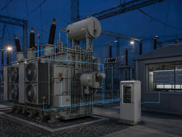
Monitoring is useful when it reduces uncertainty before an operating, inspection or maintenance decision.
A complete scope may combine thermal, electrical, chemical and mechanical indicators. It should keep the original measurement, sensor health, timestamp and operating context visible behind every alarm or health summary.
Continuous online transformer monitoring closes information gaps between inspections, but it does not replace oil sampling, offline diagnostic testing or engineering review. The project must define how an abnormal trend will be confirmed and who owns the response.
Keep specialist measurements distinct while coordinating acquisition, time, alarms and station interfaces.
Each sensor measures one defined condition at a named physical location.
Signal-specific hardware conditions, timestamps, stores and validates data.
SCADA receives selected actionable values while detailed records remain available to specialists.
Alarm ownership and confirmation methods convert data into proportionate action.
Select only the disciplines that address a credible asset risk and can support a defined response.
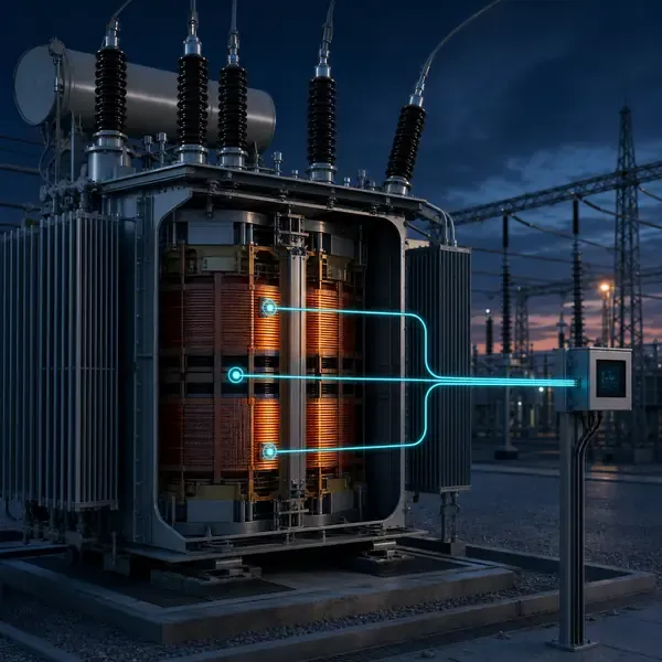
Measure transformer winding temperature with fiber optic probes, RTDs, indicators and project-configured monitoring instruments.
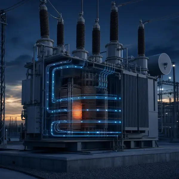
Measure selected transformer winding hot spots with direct probes, thermal context and multi-channel temperature acquisition.
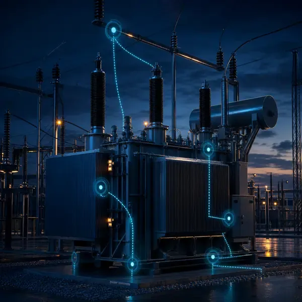
Combine UHF, ultrasonic and HFCT sensing with synchronized acquisition, PRPD patterns and persistent transformer PD alarms.
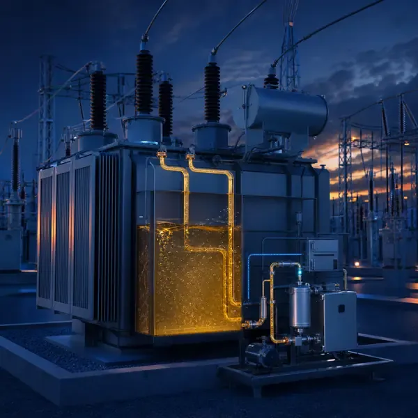
Online transformer dissolved gas analysis for fault-gas trends, rate-of-change alarms and condition-based oil sampling.
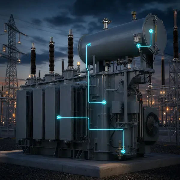
Coordinate transformer oil temperature, level, pressure and moisture-related measurements for early operating-condition awareness.
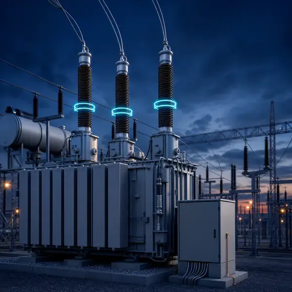
Monitor transformer bushing insulation condition through capacitance, dielectric loss, leakage current, temperature and comparative trends.
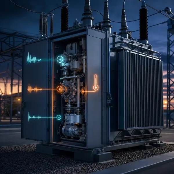
Monitor tap changer switching time, motor current, vibration, position and compartment temperature for early fault warning.
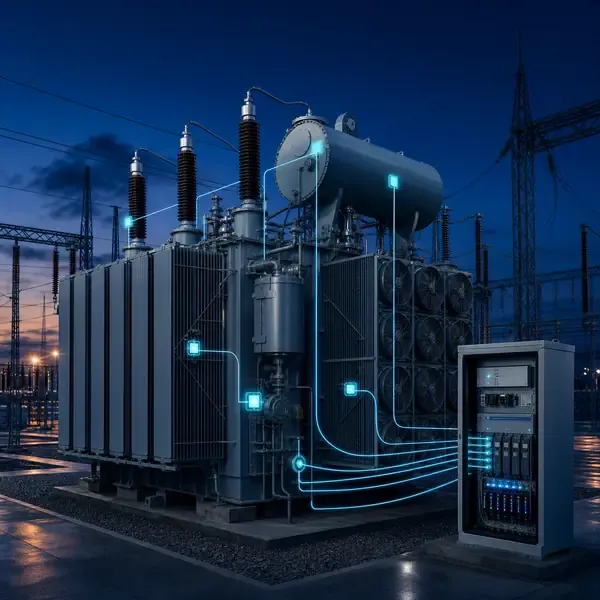
Combine transformer temperature, DGA, partial discharge, oil, bushing, OLTC and cooling evidence in one coordinated monitoring architecture.
Use the failure question, evidence type and installation boundary to compare scope—not the number of dashboard features.
| Condition question | Evidence required | Monitoring approach | Project boundary |
|---|---|---|---|
| Winding thermal stress | Direct winding or hot-spot temperature | Embedded fiber optic probes; WTI/OTI context | New-build probes normally require factory coordination |
| Insulation discharge | UHF, HFCT, acoustic and PRPD evidence | Partial discharge monitoring | Survey interference and retain raw diagnostic records |
| Oil and paper fault activity | Individual fault gases, generation rate and oil context | Online DGA plus laboratory confirmation | Define gas set, oil loop and analysis interval |
| Bushing insulation change | Capacitance, dielectric loss, leakage current and temperature | Bushing condition monitoring | Preserve safe test-tap grounding and protection |
| Tap changer degradation | Motor current, vibration, timing, position and temperature | OLTC monitoring | Compare equivalent raise/lower operations and steps |
| Fleet and station visibility | Selected values, device health, alarms and retained diagnostics | Integrated monitoring and SCADA | Define data ownership, timestamps and alarm responsibility |
New transformers allow direct winding probes, planned feedthroughs, coordinated sensor routing and factory acceptance testing. The monitoring channel schedule should be reviewed before active-part assembly.
Retrofit projects begin with safe access, existing gauges, available valves, grounding conductors, bushing test taps, OLTC drive signals, auxiliary power and outage constraints. External measurements are generally easier to add than embedded sensors.
Hardware follows the measurement scope. Review model-specific specifications only after the required condition, location and interface are defined.
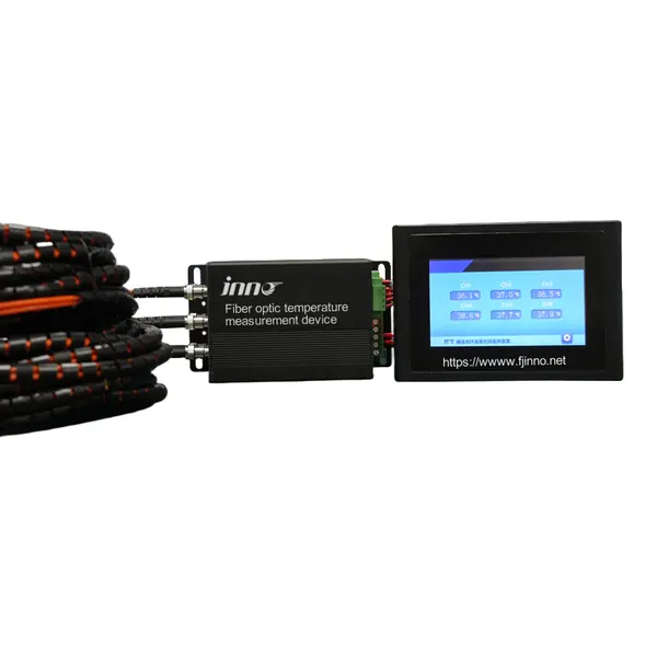
A configurable optical signal monitor for multiple transformer temperature probes.
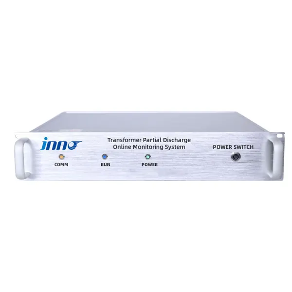
Online UHF, ultrasonic and pulse-current monitoring for transformer insulation discharge trending and early warning.
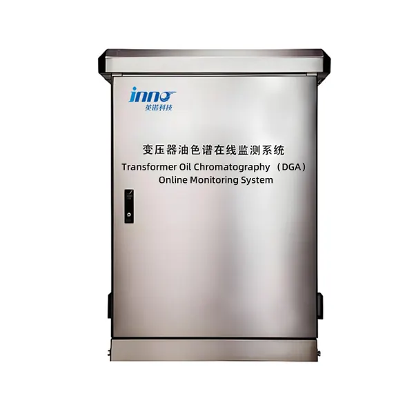
Automated oil sampling, gas separation and chromatographic analysis for transformer diagnostics.
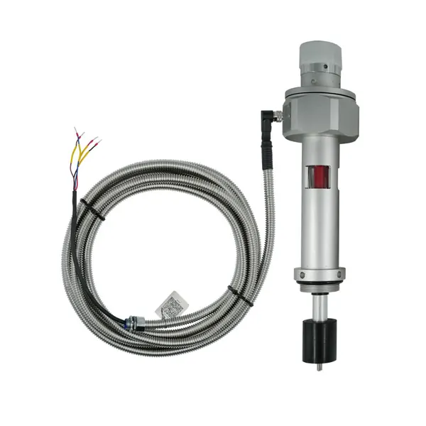
IP68 three-in-one transformer monitor for oil temperature, oil level and absolute pressure with RS-485 integration.
A comparable proposal needs more than a list of parameters. Define the complete measurement and delivery boundary.
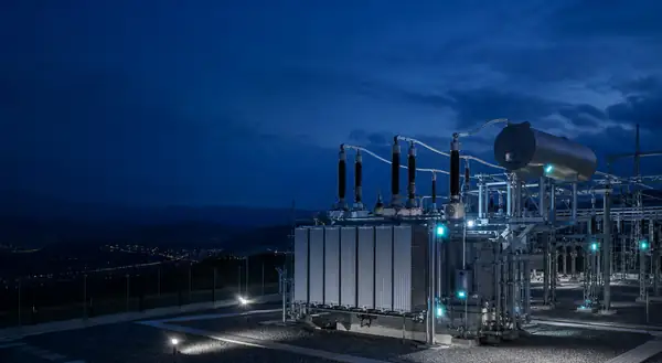
Share the transformer design, measurement points, installation stage and communication requirements. FUZHOUINNO will review a suitable product and monitoring configuration.