1. Pre-Installation Planning for Transformer Monitoring
A transformer can pass a scheduled inspection and still develop overheating, gas generation or insulation activity before the next visit. Separate gauges make the problem harder because no one sees the measurements on the same timeline. This matters to EPC engineers, commissioning teams, transformer OEMs and site supervisors.
Start by naming the transformer component, the expected fault or operating change, and the decision the measurements must support. The scope for transformer monitoring system installation must remain tied to that purpose.
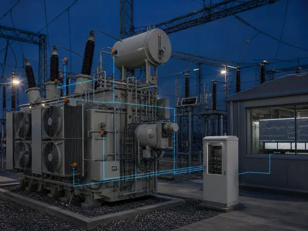
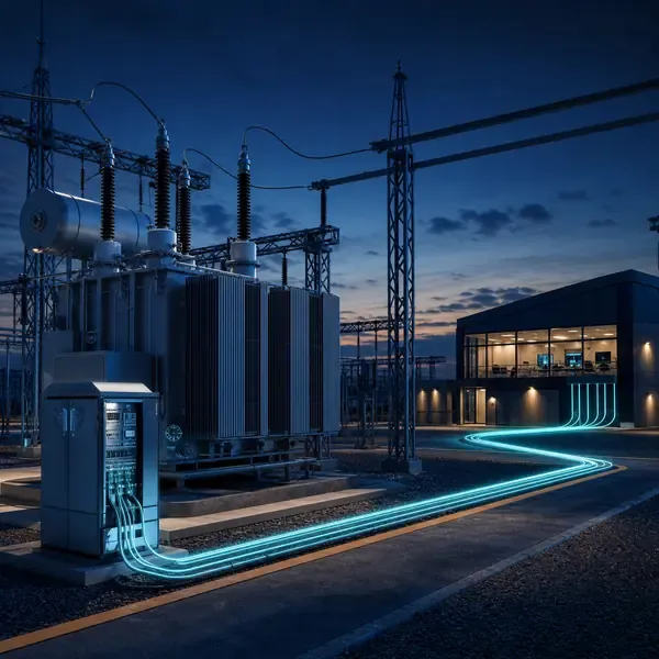
An online system brings selected temperature, oil, gas, discharge and mechanical signals into field acquisition equipment. Each channel keeps its own sampling method, device status and history while the control room receives a smaller set of alarms and operating values. The measurement path must remain traceable from sensor to alarm.
Useful evidence comes from approved sensor locations, channel identification and cable and feedthrough routing. These measurements should help the owner make sensor placement, routing, interfaces and commissioning traceable before site work begins.
A good result is not another dashboard value. It is a clear answer about what must be installed at the factory, supported by measurements that the maintenance team can check.
Installation planning should end with marked drawings, a cable and oil-tube schedule, a field cabinet layout, an outage task list and a test procedure that follows every signal to its final display.
2. Sensor and Field Unit Installation Locations
Installation quality determines whether the measurement is usable. Sensor position, bend radius, shielding or dielectric isolation, oil-loop integrity, cable separation, grounding, channel labels and safe service access must match the approved drawings and commissioning record.
An online system brings selected temperature, oil, gas, discharge and mechanical signals into field acquisition equipment. Each channel keeps its own sampling method, device status and history while the control room receives a smaller set of alarms and operating values. Record where each value originates and which operating condition can change it.
Field acquisition: conditions, timestamps and stores the signal. Verification point: Channel map, clock check and retained history. Keep the channel identity, units, timestamp and instrument status with the result.
Mixing channel labels between drawings and software can make a correct instrument look misleading. Check the measurement method and the transformer state before assigning a fault.
Sensor placement must respect the physical quantity and safe access. Confirm oil flow at DGA or moisture points, dielectric requirements for winding probes, approved test-tap interfaces for bushings and stable mounting for vibration or acoustic sensors.
3. How to Route Fiber, Signal Cable and Oil Tubing Safely
Installation quality determines whether the measurement is usable. Sensor position, bend radius, shielding or dielectric isolation, oil-loop integrity, cable separation, grounding, channel labels and safe service access must match the approved drawings and commissioning record.
Alarm layer: applies threshold, persistence and device-health rules. Verification point: Simulated advisory, warning and sensor-fault events. Keep the channel identity, units, timestamp and instrument status with the result.
Review cable and feedthrough routing together with communication status. Their direction, timing and persistence help separate a transformer change from normal operation or a sensor problem.
For cable and feedthrough routing, document the physical point, range, sampling behavior and expected output. This makes commissioning and later troubleshooting much easier.
Route optical leads within their bend limits and protect them from crushing. Separate low-level signal wiring from high-current conductors where practical, preserve shielding and grounding details, and support oil tubing to avoid strain or trapped gas.
| Monitoring layer | Concrete function | Acceptance evidence |
|---|---|---|
| Sensor layer | Measures a defined physical parameter at a named location | Drawing, sensor ID, range and realistic reading |
| Field acquisition | Conditions, timestamps and stores the signal | Channel map, clock check and retained history |
| Alarm layer | Applies threshold, persistence and device-health rules | Simulated advisory, warning and sensor-fault events |
| Station interface | Publishes selected values, quality and status | Approved tag list and communication-loss test |
4. How to Build a Channel Schedule That Matches the Drawings
An online system brings selected temperature, oil, gas, discharge and mechanical signals into field acquisition equipment. Each channel keeps its own sampling method, device status and history while the control room receives a smaller set of alarms and operating values.
The signal path for communication status runs from the sensing point through cables, optical leads or an oil loop to the acquisition unit. Local processing stores the record and sends selected values or alarms onward.
Station interface: publishes selected values, quality and status. Verification point: Approved tag list and communication-loss test. Keep the channel identity, units, timestamp and instrument status with the result.
Sampling and storage for baseline readings must match the physical event. Slow oil movement, a brief OLTC operation and a high-frequency PD pulse need different acquisition settings.
The channel schedule should match sensor labels, cable markers, terminal numbers, monitor inputs, displayed names and SCADA tags. A point-to-point check is required because a realistic value on the wrong channel can survive unnoticed.
Compare available transformer monitoring products and instruments after the sensor locations, channel quantity and required outputs are known.
5. Commissioning Alarms, Timestamps and Communication
Field example: A rising top-oil temperature is not automatically a cooling fault. If load is rising and the next fan stage starts normally, the response may be expected. If temperature continues to climb after the fan command, current feedback and stage status should be checked before the operator increases loading.
Baseline readings alone does not explain the result. Approved sensor locations provides the comparison needed to test the first explanation.
Check the affected channel, compare related measurements and confirm the operating state. The alarm procedure should then name the inspection, oil sample or offline test required for escalation.
This evidence helps determine what must be installed at the factory. Depending on severity and confidence, the next step may be continued trending, inspection, a controlled sample or an offline test.
Commissioning should test realistic readings, simulated thresholds, device-fault states, time synchronization, local storage and communication loss. Record firmware, settings and configuration files with the signed acceptance results.
6. Baseline Data Required at Handover
An actionable alarm separates absolute level, rate of change, persistence and instrument health. The setting must identify an owner and response; otherwise a threshold creates a notification but no maintenance decision.
Review approved sensor locations together with channel identification. Their direction, timing and persistence help separate a transformer change from normal operation or a sensor problem.
Field acquisition: conditions, timestamps and stores the signal. Verification point: Channel map, clock check and retained history. Keep the channel identity, units, timestamp and instrument status with the result.
After sensor replacement, oil processing or a configuration change, mark a new comparison period for approved sensor locations. Otherwise maintenance may look like sudden deterioration or recovery.
Handover data should cover representative load, ambient temperature, cooling state and recent maintenance. Capture known transitions such as fan staging or tap operation so later reviews can distinguish normal movement from a new condition.
8. Supplier Installation Responsibilities
Compare channel schedule and spare capacity and sampling and local storage by signal type before comparing price. Two proposals are not equivalent when one includes field sensors, cables, drawings and commissioning while the other lists only the monitor.
The proposal for transformer monitoring system installation should tie approved sensor locations to a model, measurement point, stated performance basis and included installation parts. This makes price differences explainable.
Installation and testing cannot remain an undefined site task. Assign responsibility for map every channel to a transformer drawing and failure mode and final review of what must be installed at the factory.
Approve equipment release only after the bill of materials, channel list, drawings, alarm behavior, tests and documents are complete. Acceptance for approved sensor locations must demonstrate the specified readings and interfaces.
The supply boundary should distinguish factory-installed parts, site-mounted sensors, cable and tubing work, cabinet installation, station wiring, software setup and commissioning. Each task needs a responsible party and an acceptance record.
Review the related transformer monitoring solution before selecting instruments for approved sensor locations.
9. What Site Information Is Needed for an Installation Quote?
Send the nameplate, general arrangement, installation stage and available drawings with the inquiry. Mark the locations related to approved sensor locations and channel identification and identify existing instruments that may be reused.
Ask how the offered equipment handles channel identification: where it is measured, how often it is recorded, which alarm uses it and what appears in the delivered test report.
Assign responsibility for separate signal, power and communication routing as required, approval of what can be retrofitted, and final acceptance.
Before production, freeze the options that affect channel identification. The order should list tests, configuration files, documentation language, commissioning records and support responsibilities.
Site information should include mounting locations, cable distances, valve and pocket details, auxiliary supplies, enclosure conditions, network interfaces and outage restrictions. Photographs support the review but do not replace marked drawings.
| Proposal item | What the buyer should verify | Why it changes the comparison |
|---|---|---|
| Channel schedule and spare capacity | Included model, quantity, performance basis and responsibility | Prevents unlike hardware scopes from appearing equivalent |
| Sampling and local storage by signal type | Drawing, interface, test method and delivered record | Prevents installation and commissioning work from becoming an unpriced change |
| Protocol, timestamps, quality flags and tag ownership | Included model, quantity, performance basis and responsibility | Prevents unlike hardware scopes from appearing equivalent |
| Cabinet power, environment and cybersecurity boundary | Drawing, interface, test method and delivered record | Prevents installation and commissioning work from becoming an unpriced change |
10. Acceptance Documents Required Before Payment
Best suited to critical, remote or heavily loaded transformers where a developing condition must be seen between routine inspections. Start with the transformer, the problem to be detected and the action expected after an alarm. The scope must clarify where the field unit should be mounted.
For cable and feedthrough routing, require the exact model, quantity, range, accessories, outputs and communication interface. Optional work should be separated from the base supply.
Split field responsibilities before ordering transformer monitoring system installation. The quotation should assign responsibility for retain local data during station-network interruption and approval of where the field unit should be mounted.
The purchase record for transformer monitoring system installation should show what arrives on site and how it will be checked. Do not replace measurable acceptance criteria with a promise to predict every failure.
Before final payment, require as-built drawings, channel and tag schedules, configuration backups, alarm tests, communication results, calibration or factory records, manuals and the initial baseline dataset.
- Channel schedule and spare capacity
- Sampling and local storage by signal type
- Protocol, timestamps, quality flags and tag ownership
- Cabinet power, environment and cybersecurity boundary
- Transformer details relevant to approved sensor locations, channel identification and cable and feedthrough routing
- Approved channel list, interfaces, tests and documentation