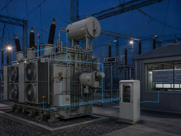
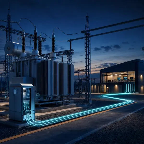
1. Transformer Monitoring Connection to SCADA
A monitor can work locally yet deliver unusable values to SCADA because of wrong scaling, stale timestamps, missing quality flags or an undefined communication-loss state. This matters to substation automation engineers, control-system integrators and asset owners.
Start by naming the transformer component, the expected fault or operating change, and the decision the measurements must support. The scope for integration of transformer monitoring with SCADA must remain tied to that purpose.
The interface maps selected measurements and alarms through an approved protocol and tag list. Detailed records remain in the field monitor while SCADA receives values that operators can act on. The measurement path must remain traceable from sensor to alarm.
Useful evidence comes from protocol status, engineering units and time synchronization. These measurements should help the owner deliver decision-relevant status to operations without losing diagnostic detail needed by maintenance.
A good result is not another dashboard value. It is a clear answer about which values enter SCADA, supported by measurements that the maintenance team can check.
2. Modbus RTU, Modbus TCP, IEC 61850 and DNP3 Compared
Modbus exposes registers, DNP3 adds utility-oriented events, and IEC 61850 uses an engineered data model rather than a simple promise of “protocol support.” Every transferred point still needs a name, unit, scaling rule, timestamp source, quality state and communication-loss behavior.
The interface maps selected measurements and alarms through an approved protocol and tag list. Detailed records remain in the field monitor while SCADA receives values that operators can act on. Record where each value originates and which operating condition can change it.
Tag model: name, units, scaling, quality and description. Verification point: Point-to-point value check. Keep the channel identity, units, timestamp and instrument status with the result.
Omitting units and scaling from the tag list can make a correct instrument look misleading. Check the measurement method and the transformer state before assigning a fault.
4. How to Define Units, Scaling, Quality and Timestamps
The interface maps selected measurements and alarms through an approved protocol and tag list. Detailed records remain in the field monitor while SCADA receives values that operators can act on.
The signal path for quality flags runs from the sensing point through cables, optical leads or an oil loop to the acquisition unit. Local processing stores the record and sends selected values or alarms onward.
Alarm: priority, persistence, acknowledgment and owner. Verification point: Simulated event and communication loss. Keep the channel identity, units, timestamp and instrument status with the result.
Sampling and storage for alarm priority and persistence must match the physical event. Slow oil movement, a brief OLTC operation and a high-frequency PD pulse need different acquisition settings.
Compare available transformer monitoring products and instruments after the sensor locations, channel quantity and required outputs are known.
5. Storage for PRPD, Waveforms and DGA Records
Field example: If a Modbus register freezes after a network interruption, SCADA must show bad or stale quality rather than a healthy last value. Reconnection testing should prove how timestamps and missed alarms are recovered.
Alarm priority and persistence alone does not explain the result. Protocol status provides the comparison needed to test the first explanation.
Approve units, scaling, data type, timestamp source, quality behavior and alarm priority for every tag. Test the complete path from field input to control-room display.
This evidence helps determine which values enter SCADA. Depending on severity and confidence, the next step may be continued trending, inspection, a controlled sample or an offline test.
6. How to Handle Communication Loss and Stale Data
A useful baseline for protocol status is recorded under known transformer conditions. A value without load, temperature, cooling or maintenance history is difficult to compare.
Review protocol status together with engineering units. Their direction, timing and persistence help separate a transformer change from normal operation or a sensor problem.
Tag model: name, units, scaling, quality and description. Verification point: Point-to-point value check. Keep the channel identity, units, timestamp and instrument status with the result.
After sensor replacement, oil processing or a configuration change, mark a new comparison period for protocol status. Otherwise maintenance may look like sudden deterioration or recovery.
7. How to Test a Transformer Monitoring Interface End to End
The control room needs concise actionable values; detailed PRPD, chromatogram and waveform records should remain accessible to specialists.
Ignoring time alignment is a significant interpretation risk for engineering units. Preserve the original reading and compare it with an independent observation before escalating.
Approve units, scaling, data type, timestamp source, quality behavior and alarm priority for every tag. Test the complete path from field input to control-room display.
This evidence helps determine who acknowledges alarms. Depending on severity and confidence, the next step may be continued trending, inspection, a controlled sample or an offline test.
- Sending unfiltered raw data to operators — check the sensor, operating state and related measurements before assigning a transformer fault.
- Omitting units and scaling from the tag list — check the sensor, operating state and related measurements before assigning a transformer fault.
- Ignoring time alignment — check the sensor, operating state and related measurements before assigning a transformer fault.
- Treating communication loss as normal data — check the sensor, operating state and related measurements before assigning a transformer fault.
8. Protocol Options to Confirm with the Supplier
Send the nameplate, general arrangement, installation stage and available drawings with the inquiry. Mark the locations related to protocol status and engineering units and identify existing instruments that may be reused.
Ask how the offered equipment handles protocol status: where it is measured, how often it is recorded, which alarm uses it and what appears in the delivered test report.
Assign responsibility for freeze the approved register or tag list, approval of which values enter SCADA, and final acceptance.
Before production, freeze the options that affect protocol status. The order should list tests, configuration files, documentation language, commissioning records and support responsibilities.
Review the related transformer monitoring solution before selecting instruments for protocol status.
9. Comparing SCADA Integration Proposals
Required for remote substations, renewable plants, industrial sites and any project where transformer alarms must enter an existing control system. Start with the transformer, the problem to be detected and the action expected after an alarm. The scope must clarify where diagnostic history remains.
For engineering units, require the exact model, quantity, range, accessories, outputs and communication interface. Optional work should be separated from the base supply.
Split field responsibilities before ordering integration of transformer monitoring with SCADA. The quotation should assign responsibility for separate diagnostic network access from operator displays and approval of where diagnostic history remains.
The purchase record for integration of transformer monitoring with SCADA should show what arrives on site and how it will be checked. Do not replace measurable acceptance criteria with a promise to predict every failure.
| Proposal item | What the buyer should verify | Why it changes the comparison |
|---|---|---|
| Network drawing and cybersecurity boundary | Included model, quantity, performance basis and responsibility | Prevents unlike hardware scopes from appearing equivalent |
| Protocol profile and exact point list | Drawing, interface, test method and delivered record | Prevents installation and commissioning work from becoming an unpriced change |
| Timestamp and quality-flag behavior | Included model, quantity, performance basis and responsibility | Prevents unlike hardware scopes from appearing equivalent |
| Integrator responsibilities and site acceptance tests | Drawing, interface, test method and delivered record | Prevents installation and commissioning work from becoming an unpriced change |
10. What Tag Lists and Configuration Files Must Be Included?
Compare timestamp and quality-flag behavior and integrator responsibilities and site acceptance tests before comparing price. Two proposals are not equivalent when one includes field sensors, cables, drawings and commissioning while the other lists only the monitor.
The proposal for integration of transformer monitoring with SCADA should tie time synchronization to a model, measurement point, stated performance basis and included installation parts. This makes price differences explainable.
Installation and testing cannot remain an undefined site task. Assign responsibility for test stale data and bad-quality flags and final review of who acknowledges alarms.
Approve equipment release only after the bill of materials, channel list, drawings, alarm behavior, tests and documents are complete. Acceptance for time synchronization must demonstrate the specified readings and interfaces.
- Network drawing and cybersecurity boundary
- Protocol profile and exact point list
- Timestamp and quality-flag behavior
- Integrator responsibilities and site acceptance tests
- Transformer details relevant to protocol status, engineering units and time synchronization
- Approved channel list, interfaces, tests and documentation