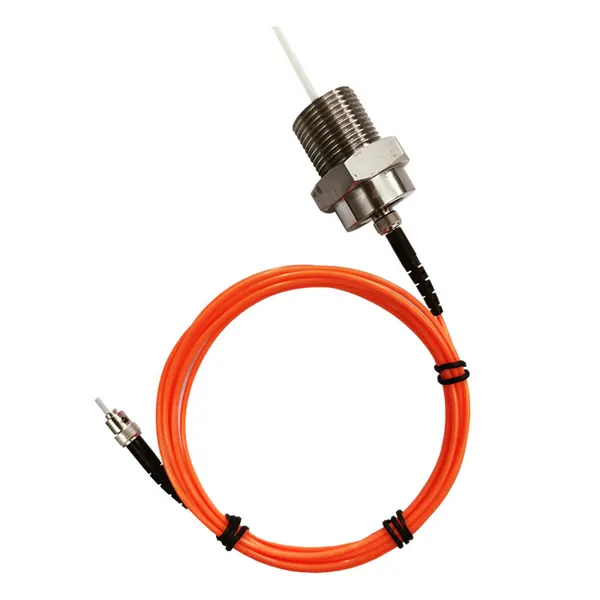
transformer fiber optic temperature sensor
Armored Fiber Optic Temperature Sensor for Oil-Immersed Transformer Windings
Armored fluorescent fiber optic sensing for direct winding hot-spot temperature measurement in oil-immersed power transformers.

Use dielectric fiber optic probes for direct transformer winding and hot spot temperature monitoring in high-voltage and strong electromagnetic environments.
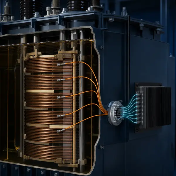
Compare available sensors and instruments that can support this project scope.
Armored fluorescent fiber optic sensing for direct winding hot-spot temperature measurement in oil-immersed power transformers.
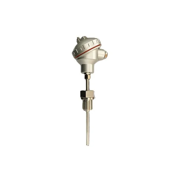
PT100 resistance temperature sensor for transformer oil and accessible thermal monitoring points.
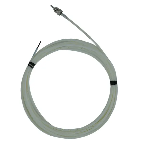
Dielectric winding-tube sensor for direct transformer hot-spot measurement in strong electromagnetic fields.
fiber optic temperature monitoring
Metallic sensors and electrical leads are unsuitable at many high-voltage winding locations. A calculated hot-spot value can also miss the actual temperature at a local conductor region.
A fluorescent sensing tip is excited by light through a dielectric fiber. Its temperature-dependent decay time is converted into a reading by the monitor, so the sensing point contains no energized electrical circuit.
Fluorescent fiber optic probes use an electrically passive sensing tip inside the winding. The monitor excites the probe optically and converts temperature-dependent fluorescence decay into a temperature value without placing a metallic electrical sensor at the high-voltage measurement point.
Fiber optic temperature monitoring uses an electrically passive fluorescent sensing tip at a selected transformer winding location. The optical monitor excites the sensor and calculates temperature from fluorescence decay, allowing direct measurement in a high-voltage electromagnetic environment without placing a metallic electrical sensing element at the conductor region.
| Measurement-chain element | Engineering purpose | Acceptance evidence |
|---|---|---|
| Embedded fluorescent probe | Measures temperature at a named winding or hot-spot location | Probe-location drawing, sensor ID and realistic temperature response |
| Optical lead and feedthrough | Carries the dielectric optical path through the active part and tank wall | Bend-radius, protection, sealing and channel-continuity record |
| Multi-channel optical monitor | Demodulates, timestamps and stores each probe value | Channel map, stated range, update rate and device diagnostics |
| SCADA interface | Publishes selected temperatures, alarms and device health | Approved tag list, scaling, timestamp and communication-loss test |
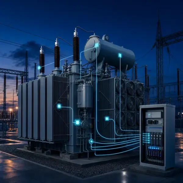
Protected probe leads route through the active part to an approved tank feedthrough and optical extension cable. A matched multi-channel monitor identifies each physical winding location, stores time-stamped values and provides project-selected relay, analog or digital outputs.
A fluorescent sensing tip is excited by light through a dielectric fiber. Its temperature-dependent decay time is converted into a reading by the monitor, so the sensing point contains no energized electrical circuit.
If one optical channel jumps while adjacent probes and top oil remain stable, inspect connector cleanliness, bend radius and optical signal strength. A real winding event normally has a plausible relationship with load, cooling or nearby points.
Keep the probe drawing, channel label, feedthrough position and optical diagnostics together. This makes it possible to separate a hot winding location from a damaged lead or poor connector.
Probe location, mechanical protection, minimum bend radius, lead routing, feedthrough construction and channel naming must be agreed with the transformer designer before winding manufacture or major overhaul.
Commissioning should prove each channel with a realistic input, confirm the channel name and units, simulate alarms and record the first usable baseline.
Alarm settings must reflect sensor location, insulation system, cooling stage and the difference between a local winding point and a bulk-oil measurement. Channel failure, broken fiber and abnormal temperature require separate event states.
Selected winding temperatures, maximum channel, device health and alarm status can enter SCADA. Higher-resolution temperature-rise test records and channel diagnostics should remain available for engineering review.
Choose fiber optics for factory-embedded winding and hot-spot measurements, high-voltage laboratories and locations with strong electromagnetic interference.
Fiber optic sensing provides direct temperature only at instrumented points. It does not locate every possible hot spot or replace load, oil, ambient and cooling context.
Compare proposals line by line. Confirm the included sensors, cables, field equipment, software, drawings, commissioning work and communication interface instead of comparing only the monitoring host.
The final scope depends on transformer design and project objectives. It normally combines selected sensors, field acquisition, alarms, communications and an engineering response process.
Retrofit feasibility depends on sensor access and outage constraints. External measurements are usually easier to retrofit than winding sensors installed inside the active part.
Yes when the selected field equipment supports the required interface. The protocol, tag list, network responsibility and acceptance tests must be defined.
No. Online trends reduce information gaps, while offline tests, oil samples and inspections remain important confirmation tools.
Provide transformer drawings and ratings, installation stage, required measurements, communication architecture, alarm philosophy and project quantity.
Monitoring guidance is provided for project scoping. Final sensor placement, alarm settings, interfaces and diagnostic actions depend on transformer design and owner procedures.
Share the transformer design, measurement points, installation stage and communication requirements. FUZHOUINNO will review a suitable product and monitoring configuration.