1. Why Oil Level, Pressure and Temperature Must Be Read Together
Oil level, pressure, temperature and moisture change with transformer loading and tank design. Reading one value in isolation can turn a normal thermal movement into a false alarm or hide a leak. This matters to substation operators, transformer maintenance teams and system integrators.
Start by naming the transformer component, the expected fault or operating change, and the decision the measurements must support. The scope for transformer oil level, pressure and temperature monitoring must remain tied to that purpose.
Electronic gauges and sensors track bulk oil temperature, liquid level, tank pressure and moisture. The expected relationship depends on whether the transformer is conservator type, sealed tank or nitrogen-blanketed. The measurement path must remain traceable from sensor to alarm.
Useful evidence comes from oil level, tank pressure or vacuum and top-oil temperature. These measurements should help the owner interpret related tank and oil-system indicators together instead of responding to isolated thresholds.
A good result is not another dashboard value. It is a clear answer about sensor ranges and mounting, supported by measurements that the maintenance team can check.
Oil level, pressure and temperature describe one containment and thermal system. A level change may be expected as oil expands, while the same change with abnormal pressure or leakage evidence requires a different response.
2. How Conservator and Sealed-Tank Designs Change the Measurements
Transformer construction and the required decision determine the suitable method. Relevant inputs include oil level, tank pressure or vacuum, top-oil temperature and ambient temperature.
Electronic gauges and sensors track bulk oil temperature, liquid level, tank pressure and moisture. The expected relationship depends on whether the transformer is conservator type, sealed tank or nitrogen-blanketed. Record where each value originates and which operating condition can change it.
Moisture in oil: oil loop or immersed probe. Verification point: Oil temperature and equilibrium with paper. Keep the channel identity, units, timestamp and instrument status with the result.
Using the wrong pressure reference can make a correct instrument look misleading. Check the measurement method and the transformer state before assigning a fault.
Conservator transformers separate expansion volume from the main tank and may use a magnetic level gauge, bladder or breather arrangement. Sealed tanks accommodate expansion differently, so normal pressure and level behavior must follow the actual design.
3. What Top-Oil and Local Temperature Sensors Reveal
The available measurements observe different parts of transformer oil level, pressure and temperature monitoring. No single value should be treated as a complete diagnosis.
Oil level: conservator or sealed-tank gauge. Verification point: Temperature-volume relationship and float condition. Keep the channel identity, units, timestamp and instrument status with the result.
Review top-oil temperature together with ambient temperature. Their direction, timing and persistence help separate a transformer change from normal operation or a sensor problem.
For top-oil temperature, document the physical point, range, sampling behavior and expected output. This makes commissioning and later troubleshooting much easier.
Top-oil temperature represents bulk oil near the upper tank region, while local pockets and electronic probes respond according to their position and thermal contact. Compare the reading with load, ambient and cooling operation.
| Parameter | Installation context | Interpretation context |
|---|---|---|
| Oil temperature | Top-oil pocket, flange or electronic sensor | Load, ambient and cooling stage |
| Moisture in oil | Oil loop or immersed probe | Oil temperature and equilibrium with paper |
| Oil level | Conservator or sealed-tank gauge | Temperature-volume relationship and float condition |
| Tank pressure | Sealed tank or pressure device | Temperature, relief operation and sealing system |
4. How Oil Level Follows Temperature and Float Position
Electronic gauges and sensors track bulk oil temperature, liquid level, tank pressure and moisture. The expected relationship depends on whether the transformer is conservator type, sealed tank or nitrogen-blanketed.
The signal path for ambient temperature runs from the sensing point through cables, optical leads or an oil loop to the acquisition unit. Local processing stores the record and sends selected values or alarms onward.
Tank pressure: sealed tank or pressure device. Verification point: Temperature, relief operation and sealing system. Keep the channel identity, units, timestamp and instrument status with the result.
Sampling and storage for load and cooling status must match the physical event. Slow oil movement, a brief OLTC operation and a high-frequency PD pulse need different acquisition settings.
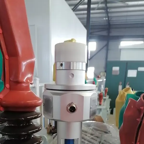
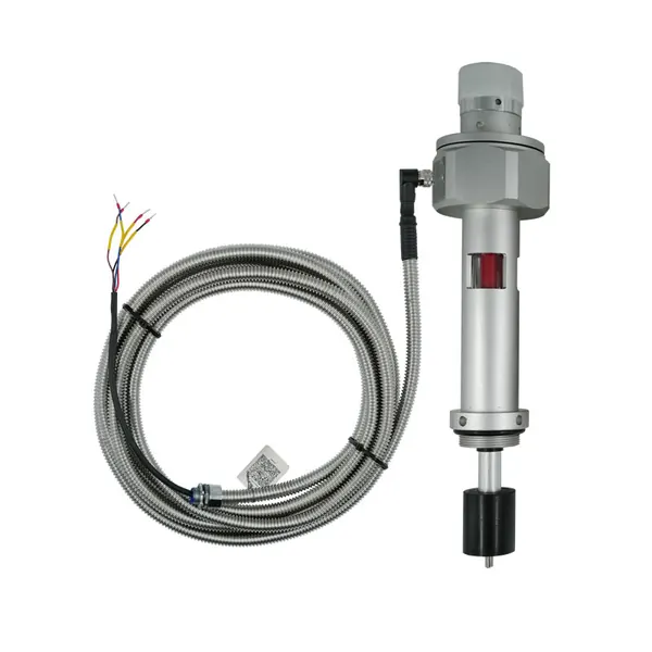
A float or magnetic mechanism converts oil movement into pointer position, alarm contacts or a transmitter signal. Linkage geometry, flange orientation and arm length must match the tank before calibration is meaningful.
Compare available transformer monitoring products and instruments after the sensor locations, channel quantity and required outputs are known.
5. What Tank Pressure and Relief Events Can Indicate
Field example: Oil level should normally move with temperature. If temperature falls but the electronic level continues to drop, compare the local gauge, inspect for leakage and verify float movement before treating the reading as a true loss of oil.
Load and cooling status alone does not explain the result. Oil level provides the comparison needed to test the first explanation.
Trend related oil values together and record the tank arrangement. Confirm contradictory readings with the local instrument, visual inspection and an oil sample where needed.
This evidence helps determine sensor ranges and mounting. Depending on severity and confidence, the next step may be continued trending, inspection, a controlled sample or an offline test.
Tank pressure rises and falls with temperature, gas space and sealing behavior. A pressure-relief operation is an event requiring inspection; a pressure transmitter is a trend input and should not be treated as the relief device itself.
6. How to Check Contradictory Gauge and Electronic Readings
A useful baseline for oil level is recorded under known transformer conditions. A value without load, temperature, cooling or maintenance history is difficult to compare.
Review oil level together with tank pressure or vacuum. Their direction, timing and persistence help separate a transformer change from normal operation or a sensor problem.
Moisture in oil: oil loop or immersed probe. Verification point: Oil temperature and equilibrium with paper. Keep the channel identity, units, timestamp and instrument status with the result.
After sensor replacement, oil processing or a configuration change, mark a new comparison period for oil level. Otherwise maintenance may look like sudden deterioration or recovery.
When local and remote readings disagree, check units, range, float movement, wiring, transmitter supply and temperature. A stuck pointer and a failed electronic output produce different patterns during an oil-temperature cycle.
7. How Alarm Contacts, 4–20 mA and Digital Outputs Are Used
An actionable alarm separates absolute level, rate of change, persistence and instrument health. The setting must identify an owner and response; otherwise a threshold creates a notification but no maintenance decision.
Ignoring gauge mechanism condition is a significant interpretation risk for tank pressure or vacuum. Preserve the original reading and compare it with an independent observation before escalating.
Trend related oil values together and record the tank arrangement. Confirm contradictory readings with the local instrument, visual inspection and an oil sample where needed.
This evidence helps determine alarm delays. Depending on severity and confidence, the next step may be continued trending, inspection, a controlled sample or an offline test.
Relay contacts provide discrete alarms, 4–20 mA carries a scaled value and digital communication can add status or diagnostics. The tag list should state the measured parameter, scaling, alarm state and response to an open circuit.
- Reading level without temperature context — check the sensor, operating state and related measurements before assigning a transformer fault.
- Using the wrong pressure reference — check the sensor, operating state and related measurements before assigning a transformer fault.
- Ignoring gauge mechanism condition — check the sensor, operating state and related measurements before assigning a transformer fault.
- Assuming a stable digital value proves tank integrity — check the sensor, operating state and related measurements before assigning a transformer fault.
8. Which Multi-Parameter Device Fits the Transformer Tank?
Compare tank and conservator design and mounting dimensions and measurement range before comparing price. Two proposals are not equivalent when one includes field sensors, cables, drawings and commissioning while the other lists only the monitor.
The proposal for transformer oil level, pressure and temperature monitoring should tie oil level to a model, measurement point, stated performance basis and included installation parts. This makes price differences explainable.
Installation and testing cannot remain an undefined site task. Assign responsibility for match flange, thread, probe depth and sealing material and final review of sensor ranges and mounting.
Approve equipment release only after the bill of materials, channel list, drawings, alarm behavior, tests and documents are complete. Acceptance for oil level must demonstrate the specified readings and interfaces.
Select the device from tank construction and required outputs. Confirm whether the project needs local indication, alarm contacts, a continuous transmitter or a combined unit that preserves local reading during communication loss.
Review the related transformer monitoring solution before selecting instruments for oil level.
9. What Flange, Thread and Probe Dimensions Must Be Confirmed?
Send the nameplate, general arrangement, installation stage and available drawings with the inquiry. Mark the locations related to oil level and tank pressure or vacuum and identify existing instruments that may be reused.
Ask how the offered equipment handles tank pressure or vacuum: where it is measured, how often it is recorded, which alarm uses it and what appears in the delivered test report.
Assign responsibility for preserve local indication where required, approval of temperature compensation, and final acceptance.
Before production, freeze the options that affect tank pressure or vacuum. The order should list tests, configuration files, documentation language, commissioning records and support responsibilities.
Provide flange pattern, thread, insertion or float dimensions, arm direction, measurement span, oil compatibility, enclosure rating and environmental limits. A correct electrical output cannot compensate for incorrect mechanical geometry.
| Proposal item | What the buyer should verify | Why it changes the comparison |
|---|---|---|
| Tank and conservator design | Included model, quantity, performance basis and responsibility | Prevents unlike hardware scopes from appearing equivalent |
| Mounting dimensions and measurement range | Drawing, interface, test method and delivered record | Prevents installation and commissioning work from becoming an unpriced change |
| Relay contact, 4–20 mA or digital outputs | Included model, quantity, performance basis and responsibility | Prevents unlike hardware scopes from appearing equivalent |
| Oil compatibility and environmental protection | Drawing, interface, test method and delivered record | Prevents installation and commissioning work from becoming an unpriced change |
10. Which Contact Ratings and Remote Outputs Belong in the Order?
Useful for remote transformer inspections, sealed-tank supervision and projects replacing mechanical indication with alarm and communication outputs. Start with the transformer, the problem to be detected and the action expected after an alarm. The scope must clarify alarm delays.
For top-oil temperature, require the exact model, quantity, range, accessories, outputs and communication interface. Optional work should be separated from the base supply.
Split field responsibilities before ordering transformer oil level, pressure and temperature monitoring. The quotation should assign responsibility for verify level and pressure reference conditions and approval of alarm delays.
The purchase record for transformer oil level, pressure and temperature monitoring should show what arrives on site and how it will be checked. Do not replace measurable acceptance criteria with a promise to predict every failure.
Specify contact form and rating, analog range, protocol, auxiliary supply, cable entries and failure behavior. Commissioning should move or simulate the input and verify local indication, remote value and every alarm point.
- Tank and conservator design
- Mounting dimensions and measurement range
- Relay contact, 4–20 mA or digital outputs
- Oil compatibility and environmental protection
- Transformer details relevant to oil level, tank pressure or vacuum and top-oil temperature
- Approved channel list, interfaces, tests and documentation